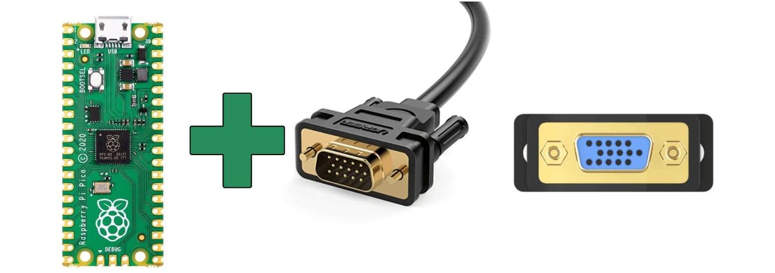
As the Raspberry Pi Pico does not have a built-in VGA output. One option is to use a VGA in Pico, which can be connected to the Pico via the GPIO Pins, Pico allows you to interface with a VGA monitor. This article will show you how to wire up the Pico to the monitor and how to program it to display text on the screen.
You will need to write software for Raspberry Pi Pico to generate the video signal, which can be done using C or Python. Libraries and modules are also available that can simplify the process.
Note – Driving a VGA display with a Raspberry Pi Pico can be a complex project, and may require some amount of programming experience.
Hardware required:
- Raspberry Pi Pico
- VGA monitor
- 8k -ohm resistor
- 4k-ohm resistor
- 2k-ohm resistor
- 1k-ohm resistor
- 0.5k ohm resistor
- 47k-ohm resistor
- VGA connector
- Breadboard
- Jumper wires
The only reason for diodes, resistors and the ( MIni Pot-Trimmer) is just to drop the Voltage to 0.7 v ( required levels ) for LCDs & Monitors.
The interface of a VGA
The most common interface signals in a VGA controller are:
- Pixel Clock or VGA Clock
- HSYNC and VSYNC signals
- For the VGA display chosen, you need to first calculate the frequency of the Pixel Clock needed to drive it. It depends on 3 parameters: The number Of Horizontal Pixels, the Number Of Vertical Pixels, and Screen Refresh Rate.
Typically, F = THP * TVP * Refresh Rate
2. HSYNC and VSYNC signals are generated from the Pixel clock. The timing of HSYNC and VSYNC signals are controlled by a number of parameters:
” Horizontal and Vertical Frontporch, Vertical and Horizontal Backporch, Vertical and Horizontal Display Pixels, Vertical and Horizontal Sync Pulse Widths and Polarities.”
Raspberry Pi Pico VGA
This particular example uses the PIO (programmable I/O) on RP2040 Chip to output a commonly used 16-bit RGB data format (RGB-565), and these digital outputs then need to be converted to three analogue output signals:
one for each colour. RGB-565 uses five bits each for the red and blue channels, and six bits for the green. In addition to these 16 data bits, VGA monitors also require HSYNC (horizontal synchronization) and VSYNC (vertical synchronization)signals for horizontal and vertical blanking timing.
The Raspberry Pi Pico comes with 5-bit DACs for RGB signals, allowing for a combination of 32,768 colours. The software support is used from the pico-playground GitHub repository.
We’ll use a 15-bit format of 5 bits red, 5 bits green and 5 bits blue with an external digital-to-analogue converter (DAC) to produce the varying colours for the VGA signal (16 bits with an extra bit for green is more usual but I only implemented 5 bits per channel on my DAC).
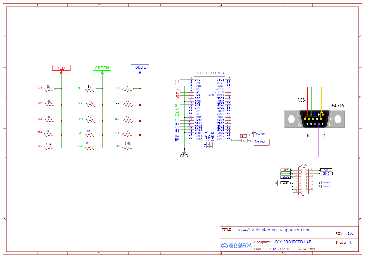
Schematic Diagram – Raspberry Pi Pico With VGA Monitor
The wiring diagram is easy and straightforward. You have to connect the Resistor pins with Pico pins as per the schematic diagram. The schematic diagram is shown below.
To build a Pico to VGA for the Raspberry Pi Pico with RP2040, you can refer to the RP2040 datasheet and the Pico’s schematic and layout, which can be found on the Raspberry Pi website. check also Getting Started Raspberry Pi Pico – Pinout, Specs – Beginner Guide
This connection for plugging a VGA monitor to a Raspberry Pi Pico, according to https://github.com/raspberrypi/pico-playground
In this circuit design, we provide 5bits of red colour, and 5bits of green and 5bits of blue on the Raspberry Pi GPIOs, These signals are summed by a resistor-based digital-to-analogue converter circuit for a total of 256 colours. Two additional analogue signals are generated for the horizontal and vertical sync pulses.
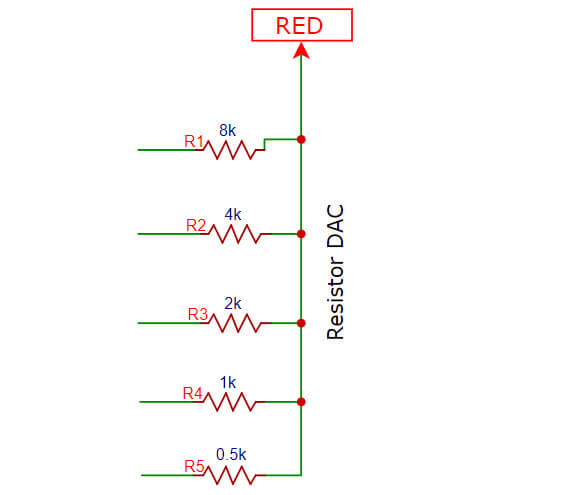
Resistor DAC In Raspberry Pi Pico With VGA Monitor
Digital-to-Analogue Converter, or DAC, is a data converter which uses two precision resistors to convert a digital binary number into an analogue output signal which is proportional to the value of the digital number.
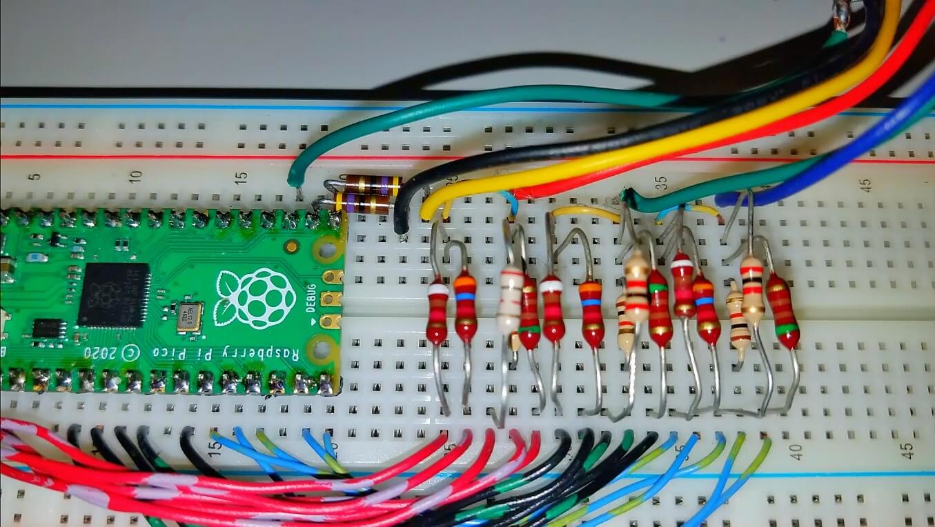
The resistors used in the DAC are specified as 500, 1000, 2000, 4000, and 8000 ohms. The three most significant bits use exact values and are closed for the two least significant bits. it only affects the colour balance a little.
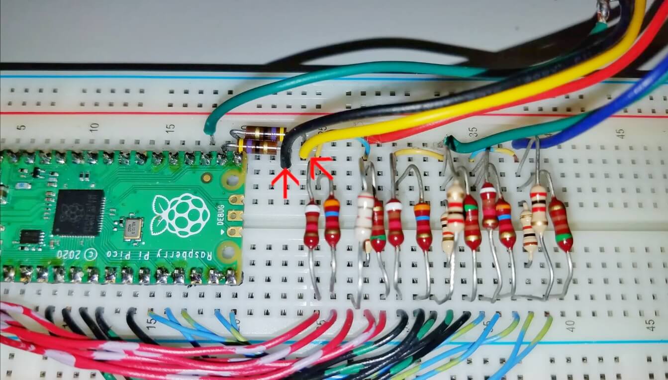
Assemble the circuit by following the schematic diagram given in the above picture. To make it simpler, I have prepared a breadboard circuit for you.
VGA Connector
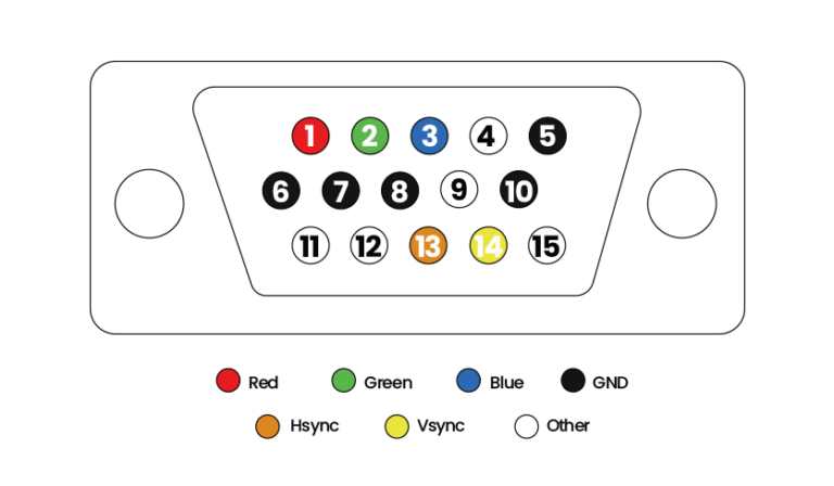
VGA (Video Graphics Array) connector is used for connecting a computer to a display device, such as a monitor, or projector. GA connector has a 15-pin connector with 3 rows each raw consisting of 5 pins. that is used to carry video signals & supports resolutions up to 640×480 pixels. VGA is an older technology, but it is still used for basic video output.
 VGA Pinout
| Pin number | Pin name | Pin description |
| 1 | Red | Red video |
| 2 | Green | Green video |
| 3 | Blue | Blue video |
| 4 | ID2/RES(N/C) | Monitor ID Bit 2 / Reserved |
| 5 | GND | Ground |
| 6 | RGND | Red Ground |
| 7 | GGND | Green Ground |
| 8 | BGND | Blue Ground |
| 9 | KEY(N/C) | +5V DC output from graphic card |
| 10 | SGND | Sync Ground |
| 11 | ID0/RES(N/C) | Monitor ID Bit 0 / Reserved |
| 12 | ID1/SDA(N/C) | Monitor ID Bit 1 / I2C bi-directional data line |
| 13 | HSYNC | Horizontal Sync |
| 14 | VSYNC | Vertical Sync |
| 15 | ID3/SCL(N/C) | Monitor ID Bit 3 / I2C data clock |
Connect Output pin to VGA cabler
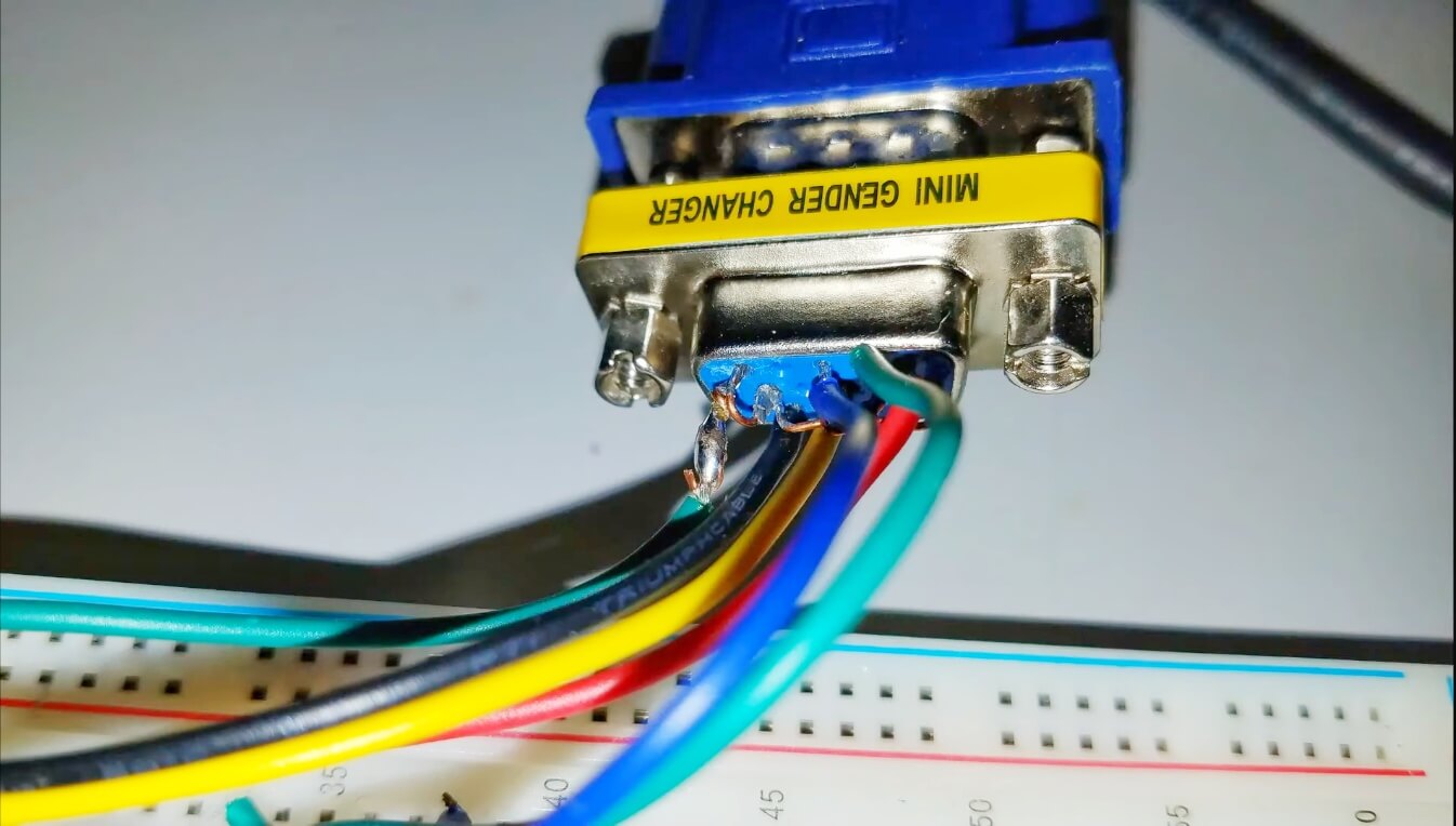
I used a VGA gender changer and connected it to my breadboard, then I connected summed red green and blue signals and added a ground to the cable.
i also connected the horizontal and vertical sync signals from the gpio pins through 47-ohm resistors
Then connected the cable to an old LCD VGA monitor.
Software
To compile C code for Raspberry Pi PICO, install these applications on a Windows desktop computer or laptop. Refer to Raspberry Pi’s Getting Started With Raspberry Pi PICO in Chapter 9.
I downloaded the pico extras and pico-playground folders from the raspberry pi github repository.
Extracted them into folders named Pico_extras and pico_playground –
- Pico extras: This folder contains various extra materials that weren’t used in the main game, such as concept art, sound files, and debug logs.
- Pico playground: This folder contains various test levels and prototypes that were used for development purposes.
Starting the command prompt. Navigate to the folder where the pico SDK & Pico extra folder is located. After locating the file you will add it to the environment
1. Then close the developer command prompt window and reopen another one.
2. Locate the pico folder, and add a build directory using mkdir.
3. Navigate into the build directory and run cmake using the following command. cmake .. -DPICO_SDK=path/to/pico_sdk/
4. After a few seconds the program should be ready to run. Then, run NMake using this command. Then, the program will automatically detect, process and show the result. If a mistake happens, go back to step
|
1 2 3 4 |
dir cd pico-playground mkdir build cmake -G "NMake Makerfiles".. |
The uf2 files to download into your pico should be inside their respective folders in the build directory. after downloading the file, open the Pico software and press the button to boot it. Next, drag and drop the UF2 file onto the Pico. The Pico software will reboot and will start the program.
Full Tutorial Video
Resources Links:
- VGA Video Interface Design: https://datasheets.raspberrypi.org/rp…
- C/C++ Application installation on Windows Computer: https://datasheets.raspberrypi.org/pi…
Raspberry Pi Video files:

