Introduction
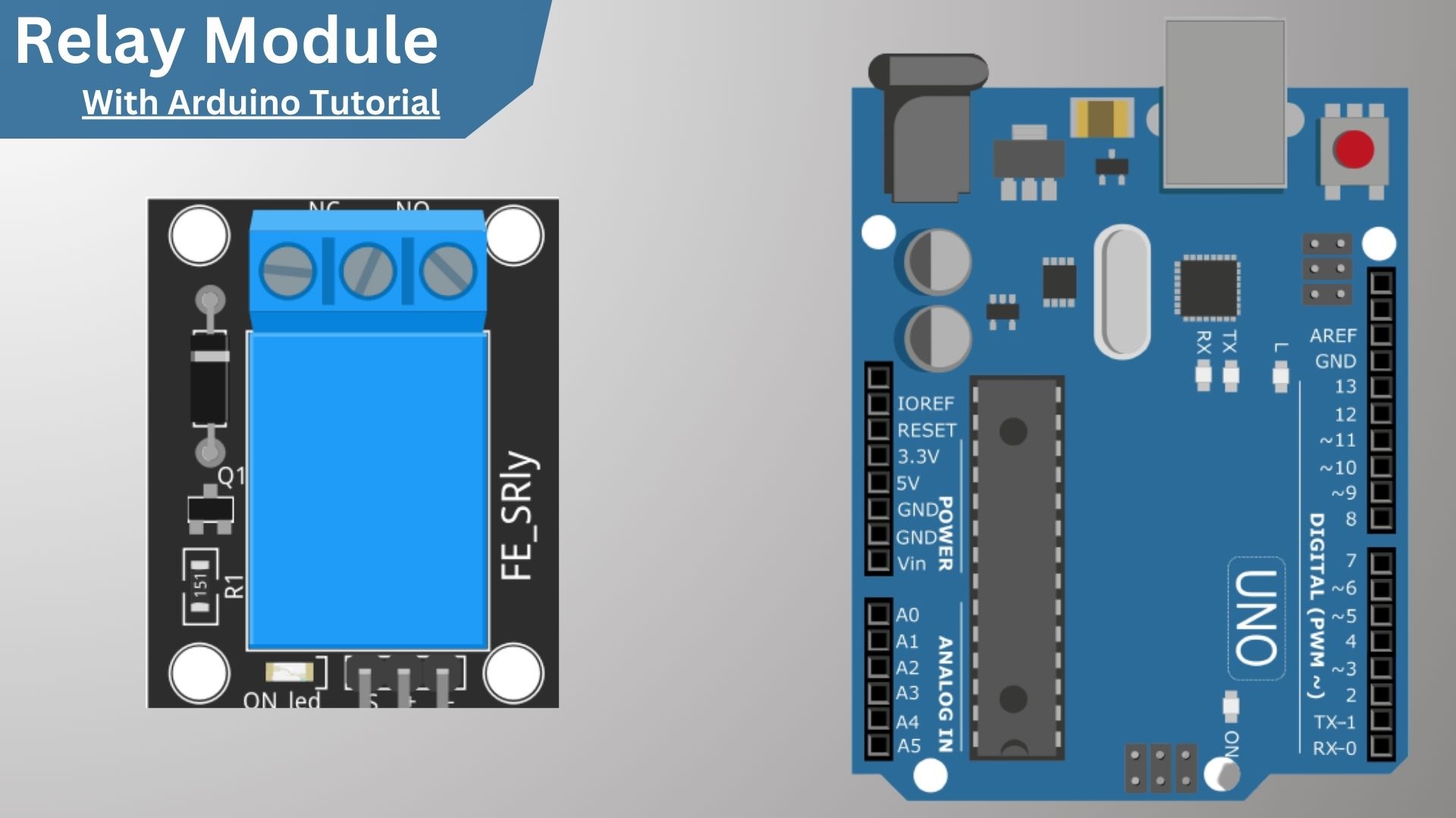
In this tutorial, we will explore how to use a Relay Module With Arduino. We will go over the basics of a Relay and how to connect it to an Arduino. We will then create a simple circuit that will turn on an LED when the relay is activated.
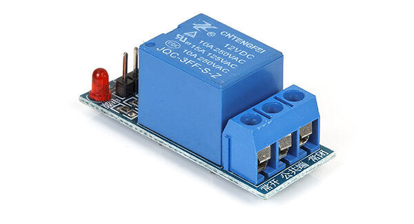
The one-channel relay module works with a voltage of 5V and can drive loads of up to 250V AC or 30V DC, supporting the highest current of 10 A. It has a power indicator LED, 2 power, and 1 control pin.
Required Materials
- 1x Arduino Uno
- 1x 5v Relay Module
- 3x Male-Female Jumpers
- 3x Electric wires
What is a Relay Module?
A relay module is an electronic control device that is used to control a switch or circuit. It is usually used in applications where a switch needs to be controlled by a computer or other electronic device. A relay module typically consists of a relay, a control circuit, and a power supply. The relay module may have one or more relays, each with its own set of contacts.
How does the Relay Module work?

Relay Module Pinout
A relay module typically has four pins: two for the coil, one for the Normally Open (NO) contact, and one for the Normally Closed (NC) contact. The coil is energized by a voltage applied to the coil pins. This creates a magnetic field that activates the relay, which then switches the position of the contacts.
- The NO (Normally Open): contact is open when the relay is not activated and closed when the relay is activated.
- The COM (Common): common pin. It is used in both normally open mode and Normally closed.
- The NC (Normally Closed): contact is closed when the relay is not activated, and open when the relay is activated.
- VCC
- Common
- Normally open
- Normally closed
- GND
Relay modules are typically labeled as follows: Coil (+) Coil (-) NO NC
How to Use a Relay Module with Arduino
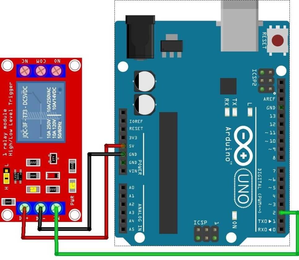
The first thing we need to do is connect the relay module to the Arduino. The relay module has three pins: two for the power supply (VCC and GND), and one for the signal input (IN1) We will be connecting the VCC and GND pins to the 5V and GND pins on the Arduino, the IN1 pin to digital pin 8 on the Arduino.
- GND: goes to ground
- IN: 2 (it will be attached to an Arduino digital pin 2)
- VCC: goes to 5V
Programming & Code – Relay Module With Arduino
Now that the relay module is connected to the Arduino, we can write a sketch to control the relay.
|
1 2 3 4 5 6 7 8 9 10 11 12 13 14 |
const int RELAY_PIN = 2; // the Arduino pin, which connects to the IN pin of relay // the setup function runs once when you press reset or power the board void setup() { pinMode(RELAY_PIN, OUTPUT); // initialize digital pin as an output. } void loop() { // the loop function runs over and over again forever digitalWrite(RELAY_PIN, HIGH); delay(500); digitalWrite(RELAY_PIN, LOW); delay(500); } |
Conclusion
- Copy the above code and open it with Arduino IDE
- Upload button on Arduino IDE to upload code to Arduino
- See LED Start blinking
Related Posts
- How to Use an LDR Sensor With Arduino Tutorial
- Explain MQ2, MQ3, MQ7 and MQ135 Gas Sensor With Arduino Tutorials
- Tutorial DS1307 RTC Module With Arduino
- Interface HC-SR04 Ultrasonic Sensor With Arduino
- Interface Rotary Encoder With Arduino, How It Works, Codes
- Interface SIM800L with Arduino Tutorial – How It Works, Codes

