Introduction
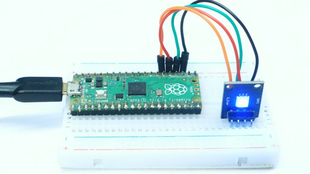
In this project, we’ll show you how to use an RGB LED Using a Raspberry Pi Pico board and control it using MicroPython. You’ll learn how to control the LED using the onboard processor, and how to control it using an external microcontroller. MicroPython is a lean and efficient implementation of the Python 3 programming language that includes a small subset of the Python standard library.
Arduino RGB LED work is fantastic! The colors and brightness are adjustable, and you can even create custom light patterns. I love how easy it is to use and how versatile it is for different projects.
Thank You NextPCB:
This project is successfully finished because of the help and sponsorship from NextPCB. Guys if you have a PCB project, please visit their website and get exciting discounts and coupons and more.
- Only 0$ for 5-10pcs PCB Prototypes:Nextpcb.com/pcbprototype
- Register and get $100 from NextPCB: Nextpcb.com/coupon
Why NextPCB
- Most Efficient, Economic, Inventive PCB Solutions
- Higher Quality
- Lower Price
- Faster Delivery
[the_ad id=”5042″]
Components Required
1. Raspberry Pi Pico Board
2. RGB LED
3. Breadboard
4. Jumper Wires
What is an RGB LED?
An RGB LED is a light-emitting diode (LED) emitting red, green, and blue light. These three colours can be mixed together in various ways to create different light colours. RGB LEDs are often used in electronic devices and appliances to create a variety of visual effects.
RGB LEDs can also be used to create unique lighting effects, and are often used in gaming keyboards and mice, as well as in computer case modding.
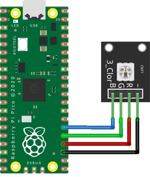
Circuit Diagram- RGB LED Using a Raspberry Pi Pico
There are a few things to keep in mind when using an RGB LED with an Arduino.
First, RGB LEDs typically have four pins: one for each colour, plus a common anode or cathode. Be sure to connect the correct wires to the correct pins! Second, when using an RGB LED with an Arduino
GPIOs 18-20 Wired to the Red, Green, and Blue LED Pins
MicroPython Code – RGB LED Using a Raspberry Pi Pico
The following code will be breathing each LED and using the PWM function, the brightness of each LED brightness increasing and decreasing. Getting Started With Raspberry Pi Pico With Thonny IDE – How to Program Pico
|
1 2 3 4 5 6 7 8 9 10 11 12 13 14 15 16 17 18 19 20 21 22 23 24 |
# import time from machine import Pin,PWM pwm_pins = [18,19,20] # set PWM pins pwms = [PWM(Pin(pwm_pins[0])),PWM(Pin(pwm_pins[1])), PWM(Pin(pwm_pins[2]))] # pwm array [pwm.freq(1000) for pwm in pwms] # set pwm freqs step_val = 64 # step value for 16-bit breathing range_0 = [ii for ii in range(0,2**16,step_val)] # brightening range_1 = [ii for ii in range(2**16,-step_val,-step_val)] # dimming while True: # loop indefinitely # looping through red, blue, green breathing for pwm in pwms: for ii in range_0+range_1: pwm.duty_u16(ii) # set duty cycle out of 16-bits time.sleep(0.001) # sleep 1ms between pwm change # white pixel breathing (all three LEDs) for ii in range_0+range_1: for pwm in pwms: pwm.duty_u16(ii) # set duty cycle time.sleep(0.001) # wait 1ms |
Similar to the code above, be certain to select F5 or Run and save the file as the new ‘main.py’ file on the Pico.
This will cause the script to run continuously, resulting in an endless ‘breathing’ appearance from the RGB LED.
References
- Raspberry Pi Documentation link
- Raspberry Pi Datasheet link
- Micropython on Raspberry Pi Pico link
- Getting Started with Micropython on Raspberry Pi Pico link
[the_ad id=”5038″]
Read Similar Articles:
- Getting Started Raspberry Pi Pico – Pinout, Specs – Beginner Guide
- Interfacing PIR Motion Sensor with Raspberry Pi Pico
- Raspberry Pi Pico Home Automation System
- Interface Servo Motor With Raspberry Pi Pico
- Interface 0.96″ OLED Display with Raspberry Pi Pico
- Raspberry Pi Pico Weather Station Using Dht11 Sensor
- Interface 16*2 LCD Display With Raspberry Pi Pico


2 Comments
Very nicely explained and well written
Pingback: Raspberry Pi Pico Projects For Beginners [2022]