Introduction
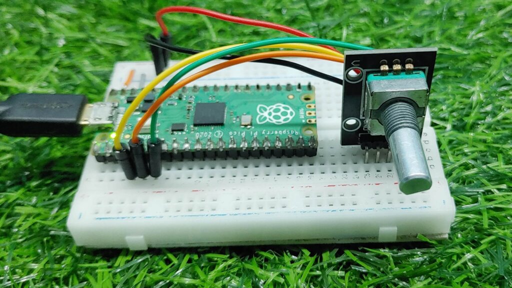
In this tutorial, we will show you how to use a Rotary Encoder with Raspberry Pi Pico. A Rotary Encoder is a device that can be used to measure the rotational movement of an object. They are often used in electronic devices such as computer mice and control knobs. In this project, we will use a Rotary Encoder with raspberry Pi Pico to control the position of a servo motor.
A rotary encoder is a device you can use to measure the rotational movement of an object. They are often used in industrial applications where precise control is required, such as CNC machines. Check this interesting project using a Rotary encoder to Control PC Volume, and Brightness Using Raspberry Pi Pico & Rotary Encoder
Thank You, PCBWay:
This project is successfully completed because of the support and help from PCBWay. Guys if you have a PCB project, please see their website and get exciting bargains and coupons.
PCBway is the best prototype PCB company offering great PCB boards at lower prices If you sign-up using this link you will get beginner and sign-up coupon rewards. https://www.pcbway.com
Required Material
What is a Rotary Encoder?
A rotary encoder is a type of mechanical sensor that is used to count the rotational movement of an object. It is generally used in applications where accurate position or speed control is required, such as in automotive, robotics, and aerospace applications.
As the shaft or wheel rotates, the sensor produces pulses of electrical power that are equal to the angular position of the shaft or wheel. One benefit of using a rotary encoder over different types of sensors is that it can be used to measure both the position and the speed of the shaft or wheel. Also, rotary encoders are relatively affordable and easy to interface with microcontrollers.
How does a Rotary Encoder work
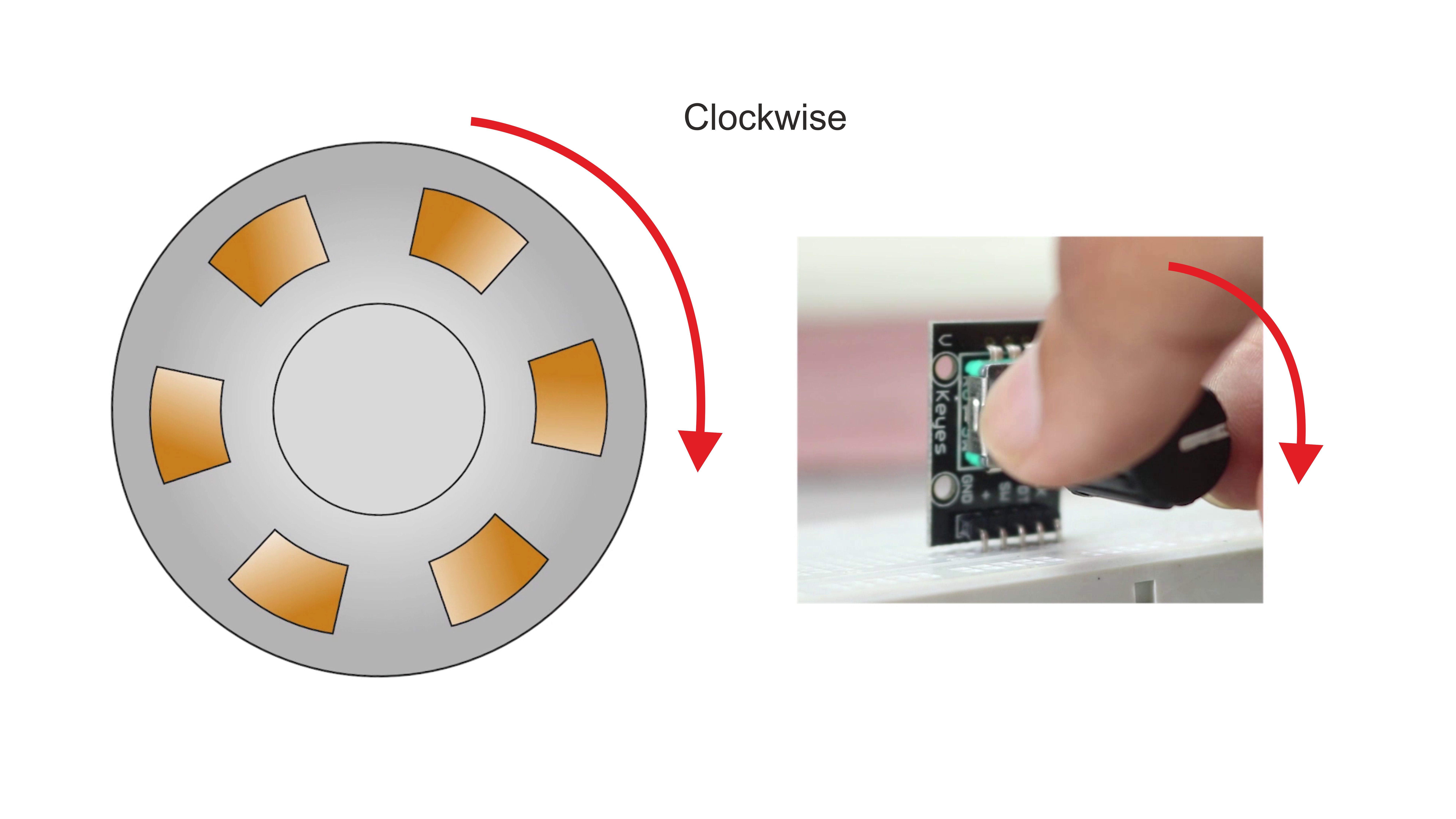
A Rotary Encoder is a device that measures the rotational movement of an object. It consists of a sensor, usually a visual or magnetic sensor, that generates electrical pulses when the object rotates. The number of pulses per revolution can be used to calculate the speed of the object, and the direction of rotation can be determined by the order of the pulses.
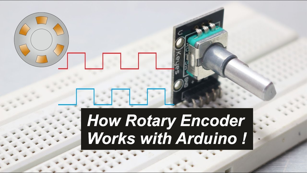
The sensor converts the rotational movement into a digital or analogue signal that can be processed by a control system. Check also How Rotary Encoder Works
Construction & Working
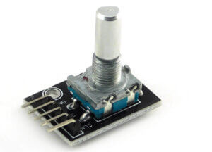
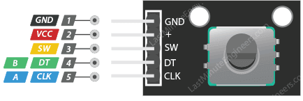
It has five pins – Clock, Data, Switch, Vcc, GND
Working:
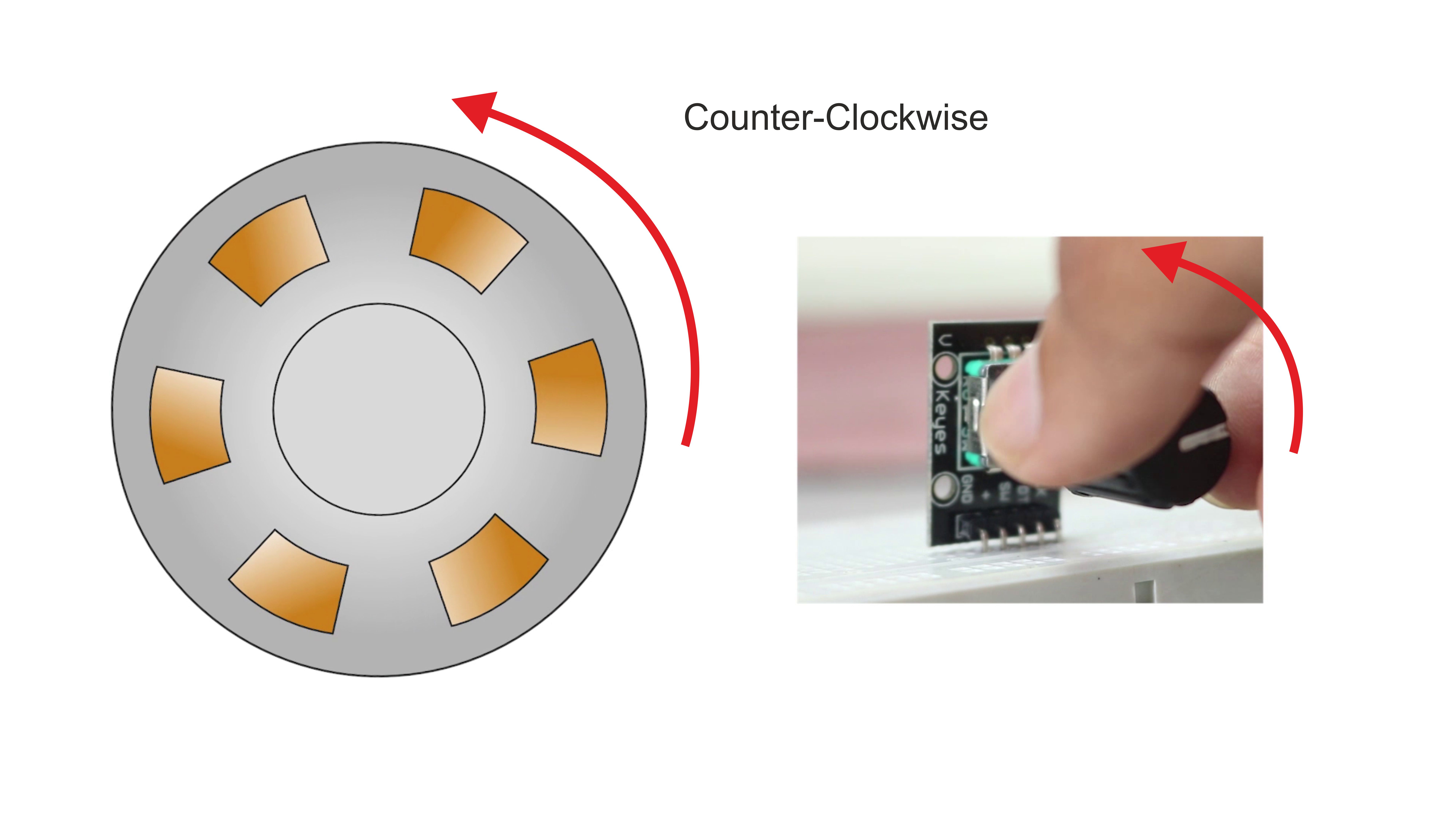
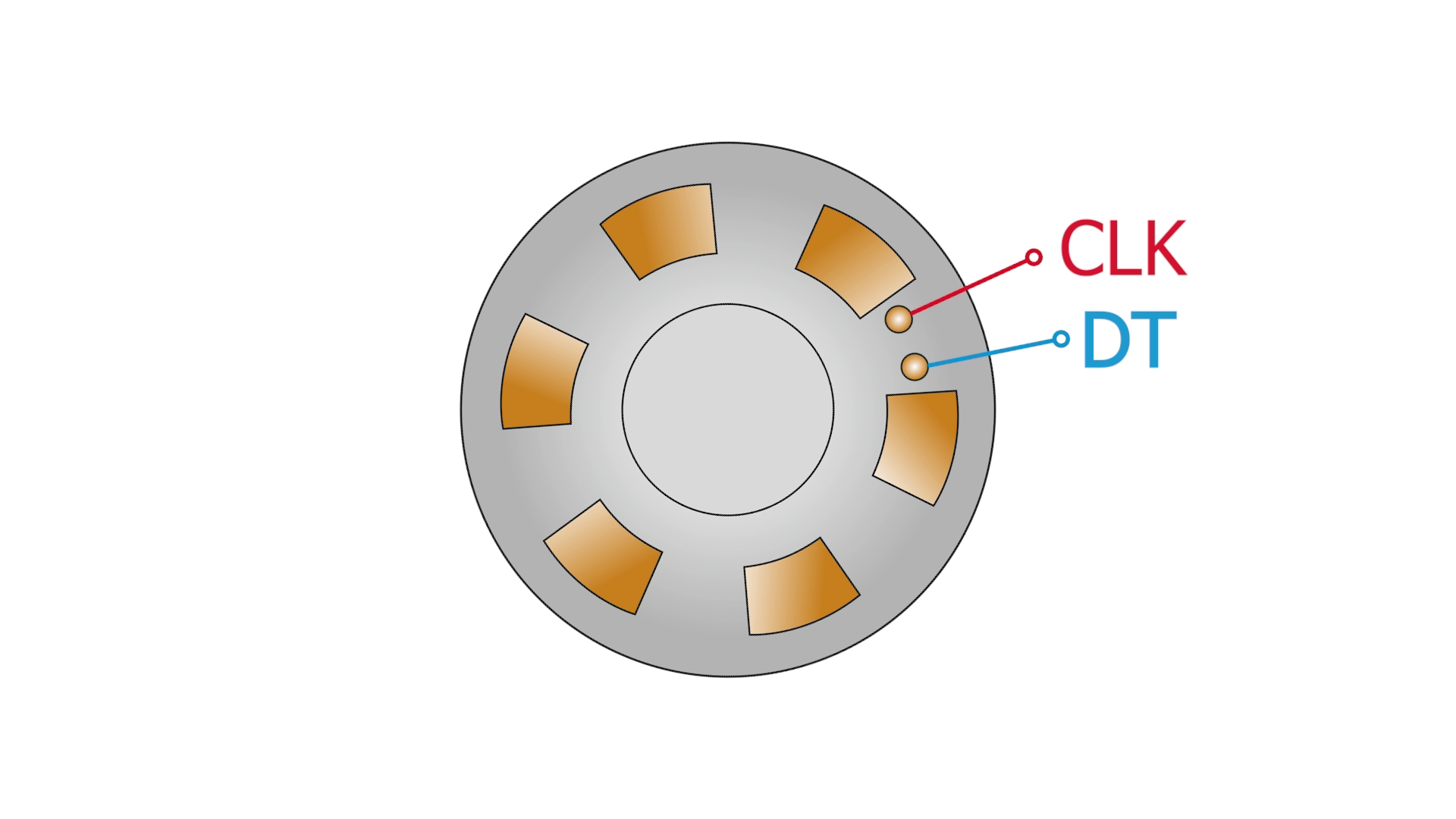
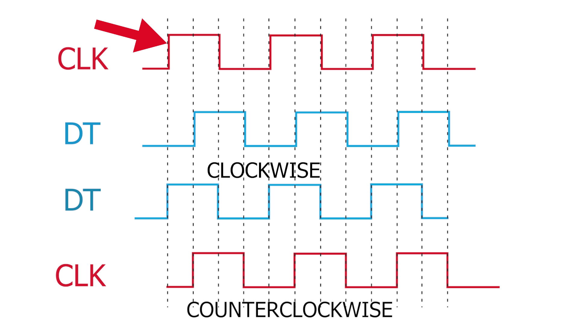
As we rotate our encoder, the two outputs will change depending on the position of the encoder. Which will generate two trains of pulses.
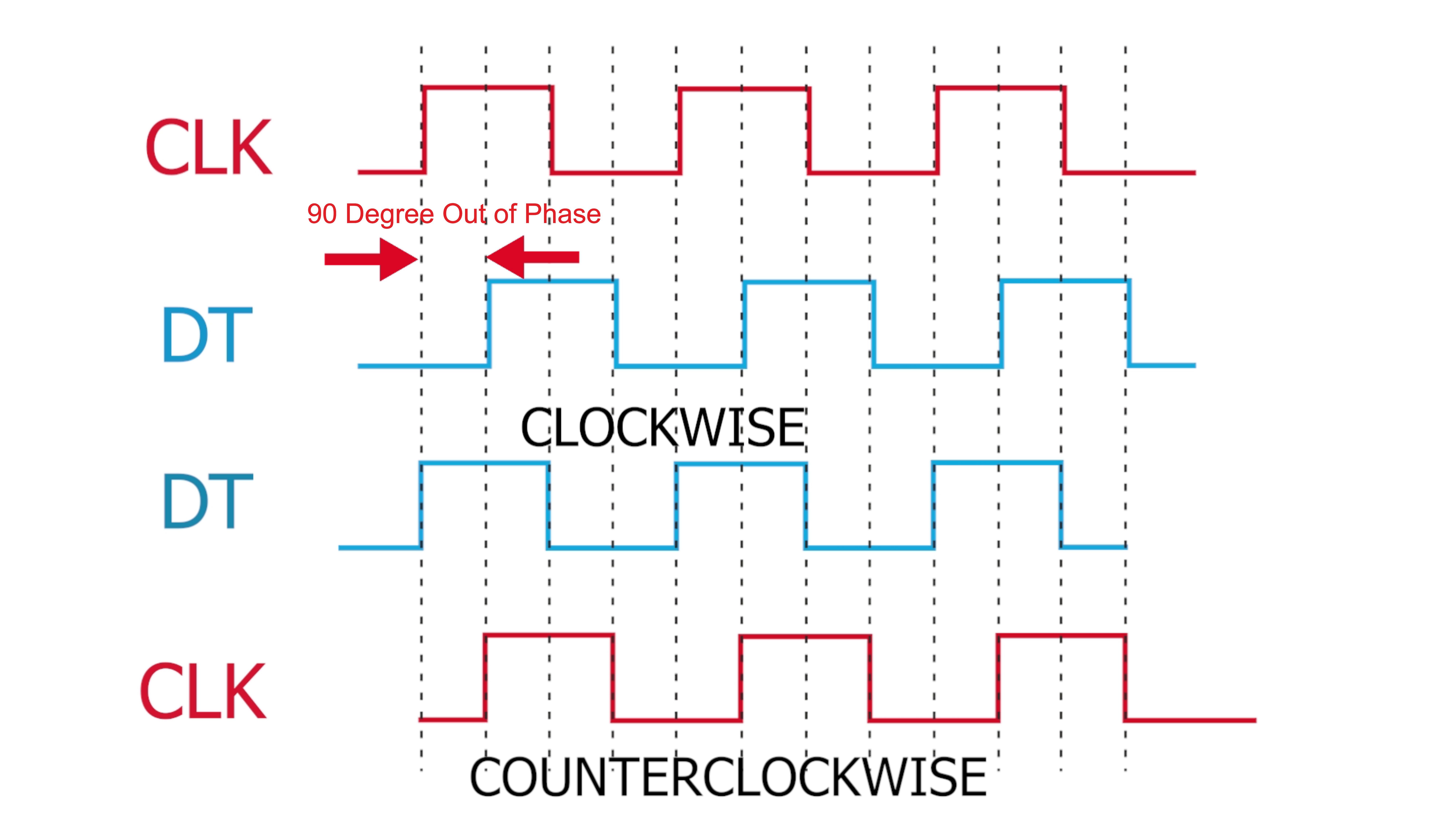
If you look closely those two signals will be 90 degrees out of the phase. If the encoder rotates clockwise then CLOCK will lead and if the encoder rotates counter-clockwise then DATA will lead.
And assuming a look at state change for clockwise two signals will have opposite values and for counter-clockwise exact values.
Rotary Encoder Pinout
Interfacing a Rotary Encoder with Raspberry pi pico
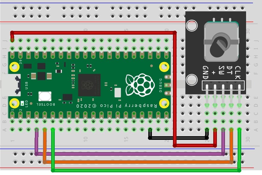
To interface a rotary encoder with the Pico, we will need to use two of the Pico’s GPIO pins. We will connect one of the GPIO pins to the encoder’s “A” output and the other GPIO pin to the encoder’s “B” output. The
The rotary encoder we will use is the KY-040 encoder. This encoder has a disk with 24 slots and a built-in push button.
Micropython Script – Rotary Encoder with Raspberry pi pico
The code for this project is written in MicroPython, which is a version of the Python programming language. Check also Getting Started With Raspberry Pi Pico With Thonny IDE
|
1 2 3 4 5 6 7 8 9 10 11 12 13 14 15 16 17 18 19 20 21 22 23 24 25 26 27 28 29 30 31 32 33 34 35 36 37 38 39 40 41 42 43 44 45 46 47 48 49 50 51 52 53 54 55 56 57 58 59 60 61 62 63 64 65 66 67 68 69 70 71 72 73 74 75 76 77 78 79 80 81 82 83 84 85 86 87 88 89 90 91 92 93 94 95 96 97 98 99 100 101 |
# interface incremental encoder with interrupts # raspberry pi pico and micropython # import libraries from machine import Pin import utime # define encoder pins switch = Pin(2, mode=Pin.IN, pull = Pin.PULL_UP) # inbuilt switch on the rotary encoder, ACTIVE LOW outA = Pin(4, mode=Pin.IN) # Pin CLK of encoder outB = Pin(3, mode=Pin.IN) # Pin DT of encoder ledPin = Pin(25, mode = Pin.OUT, value = 0) # Onboard led on GPIO 25 # define global variables counter = 0 # counter updates when encoder rotates direction = "" # empty string for registering direction change outA_last = 0 # registers the last state of outA pin / CLK pin outA_current = 0 # registers the current state of outA pin / CLK pin button_last_state = False # initial state of encoder's button button_current_state = "" # empty string ---> current state of button # Read the last state of CLK pin in the initialisaton phase of the program outA_last = outA.value() # lastStateCLK # interrupt handler function (IRQ) for CLK and DT pins def encoder(pin): # get global variables global counter global direction global outA_last global outA_current # read the value of current state of outA pin / CLK pin outA_current = outA.value() # if current state is not same as the last stare , encoder has rotated if outA_current != outA_last: # read outB pin/ DT pin # if DT value is not equal to CLK value # rotation is clockwise [or Counterclockwise ---> sensor dependent] if outB.value() != outA_current: counter += 1 direction = "Clockwise" else: counter -= 1 direction = "Counter Clockwise" # print the data on screen print("Counter : ", counter, " | Direction : ",direction) print("\n") outA_last = outA_current utime.sleep_ms(1) def button(pin): # get global variable global button_last_state global button_current_state button_current_state = True if button_current_state != button_last_state: # write some code here for button press print("Button is Pressed ","\n") utime.sleep_ms(10) # 10 millisecond sleep for button debounce , button_last_state = button_current_state outA.irq(trigger = Pin.IRQ_RISING | Pin.IRQ_FALLING, handler = encoder) # attach interrupt to the outB pin ( DT pin of encoder module ) outB.irq(trigger = Pin.IRQ_RISING | Pin.IRQ_FALLING , handler = encoder) # attach interrupt to the switch pin ( SW pin of encoder module ) switch.irq(trigger = Pin.IRQ_FALLING, handler = button) while True: ledPin.toggle() utime.sleep(1) button_last_state = False # reset button last state to false again , |
Conclusion
In conclusion, the rotary encoder with Raspberry Pi Pico is a great way to get started with physical computing. It is easy to use and has a lot of features.
Read Similar Articles:
- Getting Started Raspberry Pi Pico – Pinout, Specs – Beginner Guide
- Interfacing PIR Motion Sensor with Raspberry Pi Pico
- Raspberry Pi Pico Home Automation System
- Interface Servo Motor With Raspberry Pi Pico
- Interface 0.96″ OLED Display with Raspberry Pi Pico
- Raspberry Pi Pico Weather Station Using Dht11 Sensor
- Interface 16*2 LCD Display With Raspberry Pi Pico

