In this tutorial, we will show you how to control a stepper motor with Arduino. We will go over the basic principles of how stepper motors work, and how to connect a stepper motor to Arduino. We’ll first create a simple sketch to move the motor one step at a time. Then, we’ll add a potentiometer to our circuit so that we can control the motor’s speed.
Stepper motors are used in a variety of applications, including 3D printers, CNC mills and lathes, and robotics. check out 50+ Arduino Projects With Code
Thank You, PCBWay:
This project is successfully completed because of the support and help from PCBWay. Guys if you have a PCB project, please see their website and get exciting bargains and coupons.
PCBway is the best prototype PCB company offering great PCB boards at lower prices If you sign-up using this link you will get beginner and sign-up coupon rewards. https://www.pcbway.com
Required Materials
- Arduino UNO
- A4988 stepper motor driver
- Stepper motor
- Power supply (12V DC)
- Jumper wires
- Breadboard
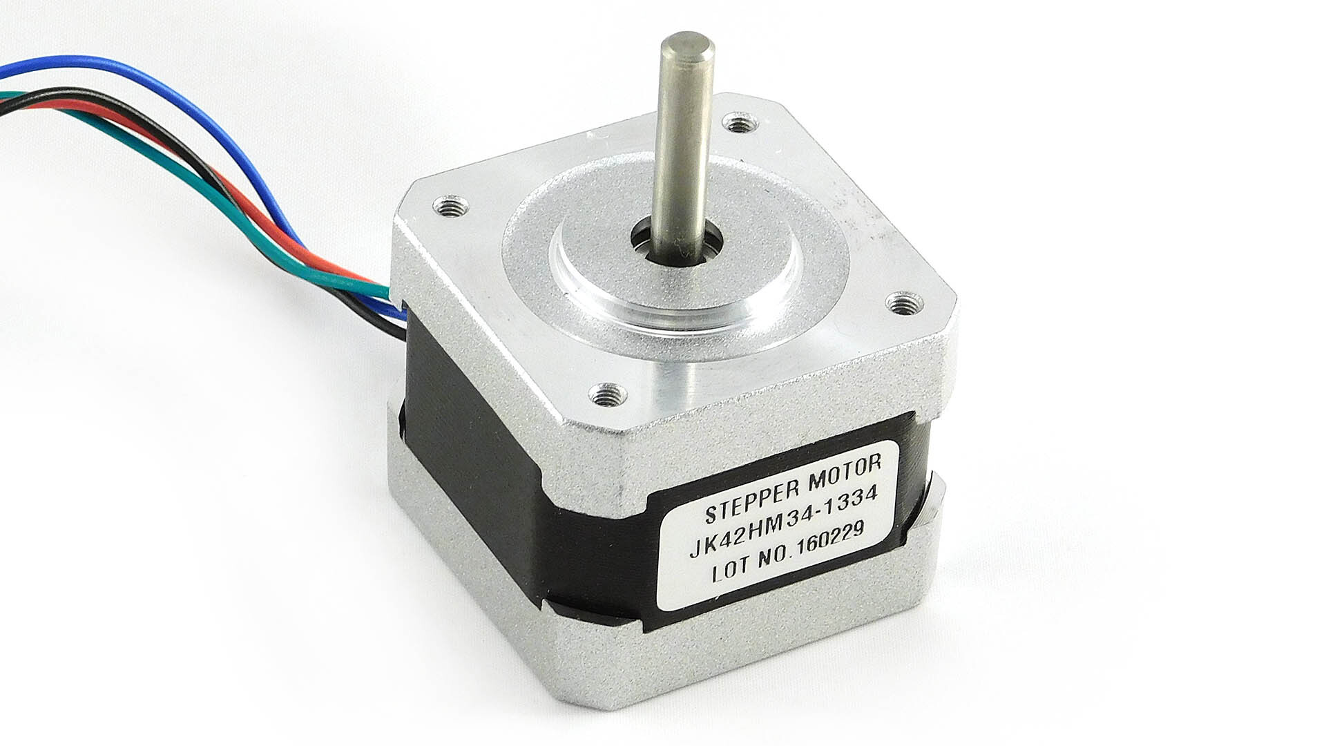
NEMA17 Stepper Motor
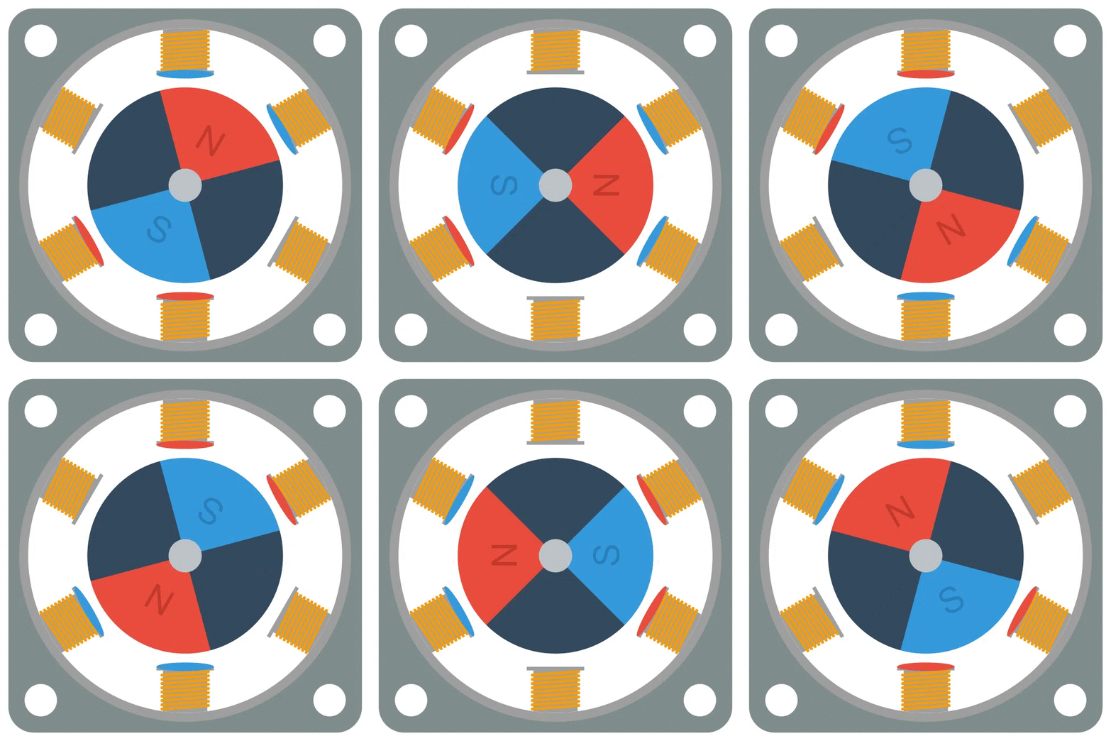
Stepper motors are a type of electric motor that can turn precise amounts in direction. They work by moving in small “steps” instead of rotating continuously like a conventional motor.
The NEMA 17 stepper motor is a type of hybrid stepping motor that has a step angle of 1.8 degrees, or 200 steps per revolution. The title “NEMA” comes from the National Electrical Manufacturers Association’s specification for stepper motors. The number “17” refers to the faceplate dimensions of the motor, which are around 1.7 inches by 1.7 inches.
A Stepper motor is an electromechanical device that converts electrical pulses into discrete mechanical movements. The shaft of a stepper motor rotates in discrete steps as electrical command pulses are applied to the motor winding coils. The size of the steps is determined by the motor design and is generally between five and thirty degrees.
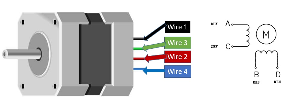
Pinout NEMA17 Stepper Motor
Specifications
- Motor Type: Single Shaft
- Step Angle: 1.8 degrees
- Holding Torque: 4.8 Kg-Cm
- Operating Voltage: 12VD
- Supply Current: 2.5 A/Phase
- Number of Leads: 4
- Inductance: 1.8 mH/Phase
- Resistance: 1.25 ohms
- Weight: 366 grams
- Dimensions (LxWxH): 42x42x48 mm
- Detent Torque: 0.28 kg-cm
- Frame Size: 42 x 42 mm
- Inductance Accuracy: ±20%
- Resistance Accuracy: ±10%
- Shaft Type: D-type
- Shaft Diameter: 5 mm (Round-side), 4.7 mm (D-side)
- Shaft Length: 22 mm
- Step Angle Accuracy: ±5%
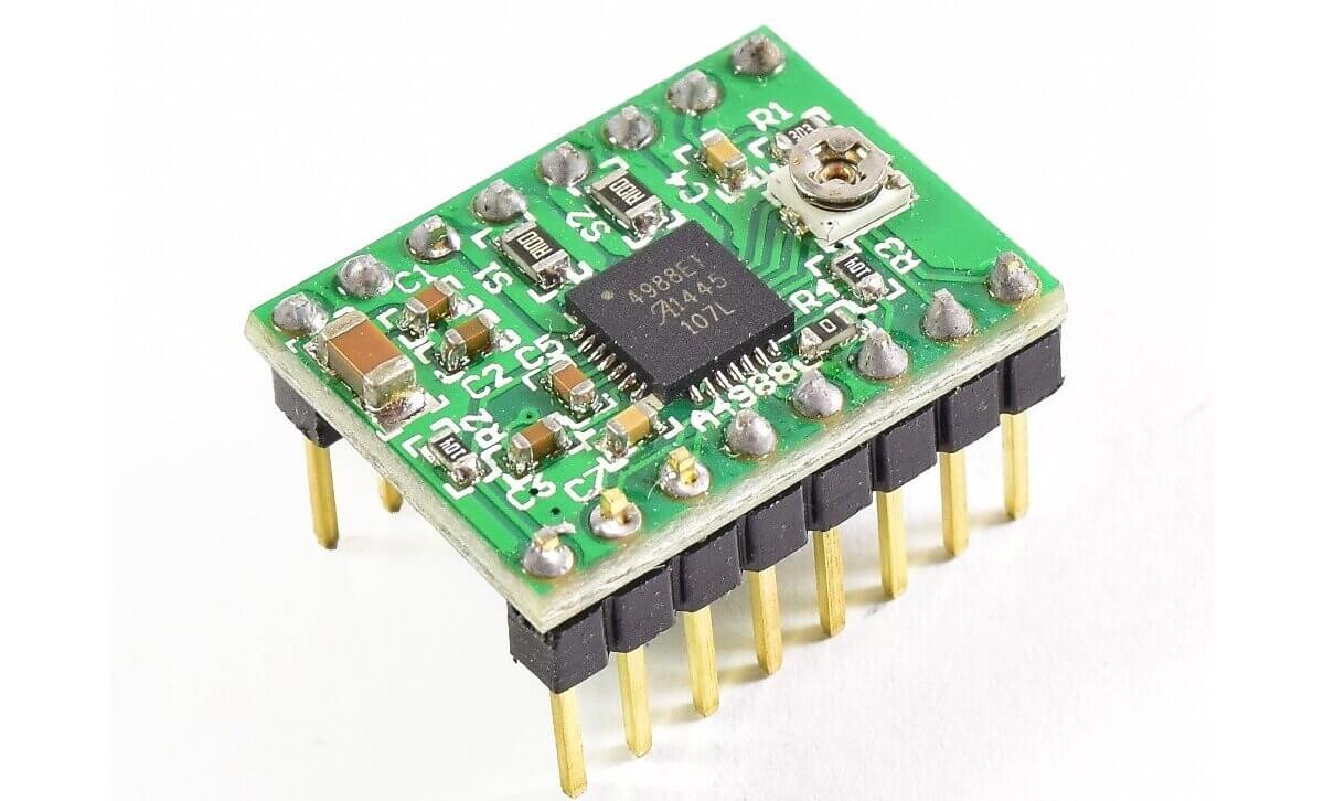
A4988 Stepper Motor Driver Board
The A4988 is a stepper motor driver board used to control the movement of stepper motors. It is capable of driving bipolar stepper motors with up to 2A of current per phase.
A4988 driver board works by using pulse width modulation (PWM) to control the current to each coil of the stepper motor. This allows users to create precise movements of the motor, allowing it to move in a selected amount of steps. For more information, you can check out the datasheet here. A4988 Datasheet
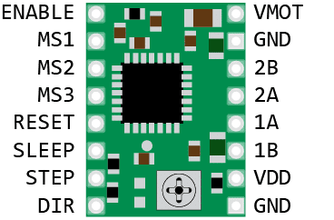
Pinout of A4988 Stepper Motor Driver
The A4988 driver has a total of 16 pins that connect it to the outside world. The A4988 driver module has a total of 16 pins as follows: The connections are as follows:
- VMOT: Power supply voltage (8-35V) pin.
- GND: Ground pin.
- VDD: 5V output pin from the onboard voltage regulator.
- RESET: Driver reset pin.
- SLEEP: Driver sleep mode pin.
- ENABLE: Driver enable/disable pin.
- MS1, MS2, MS3: Microstepping resolution selection pins.
- DIR: Motor direction control pin.
- STEP: Motor step pulse input pin.
- GND: System ground pin.
Specifications
- Operating voltage: 8-35V
- Maximum current: 2A
- Microstep resolution: Full step, ½ step, ¼ step, 1/8 and 1/16 step
- Thermal shutdown circuitry
- Overcurrent protection
- Dimensions: 15.5 × 20.5 mm (0.6″ × 0.8″)
- Adjustable current limiting
- Short-circuit protection
- Low-ESR ceramic capacitor on the output
- Low RDS(ON) outputs
A4988 driver board is a compact and efficient solution for driving stepper motors, and its adjustable current limiting and micro-stepping capabilities make it suitable for a wide range of applications, including 3D printers, CNC machines, robotics, and more.
Set current limit
When you want to control a stepper motor, you need to provide it with the right amount of current so that it can move correctly. To do this, you need to set the current limit on the stepper motor driver.
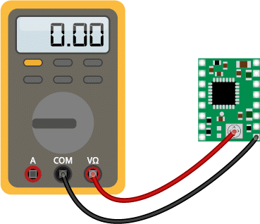
One way to set the current limit is by measuring the voltage at the “ref” pin on the driver while adjusting a potentiometer. Here’s how you can do it:
- Find the rated current of your stepper motor in its datasheet. For example, it’s 350mA.
- Disconnect the micro step selection pins on the driver so it’s in full-step mode, and hold the motor.
- Measure the voltage at the “ref” pin on the driver while adjusting the potentiometer. You want to adjust the potentiometer until the voltage matches the preferred current limit for your motor.
- Use the formula Vref = Current Limit / 2.5 to calculate the Vref voltage you need to set. For example, if your motor is rated at 350mA, you would set the Vref voltage to 0.14V (350mA / 2.5).
Remember to always study the manual or datasheet for your specific driver to ensure you are setting the current limit correctly and safely.
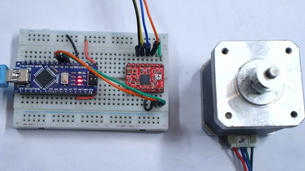
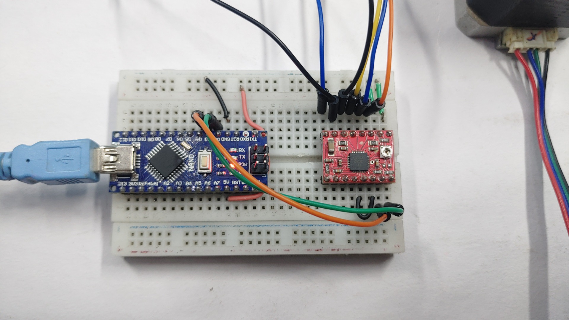
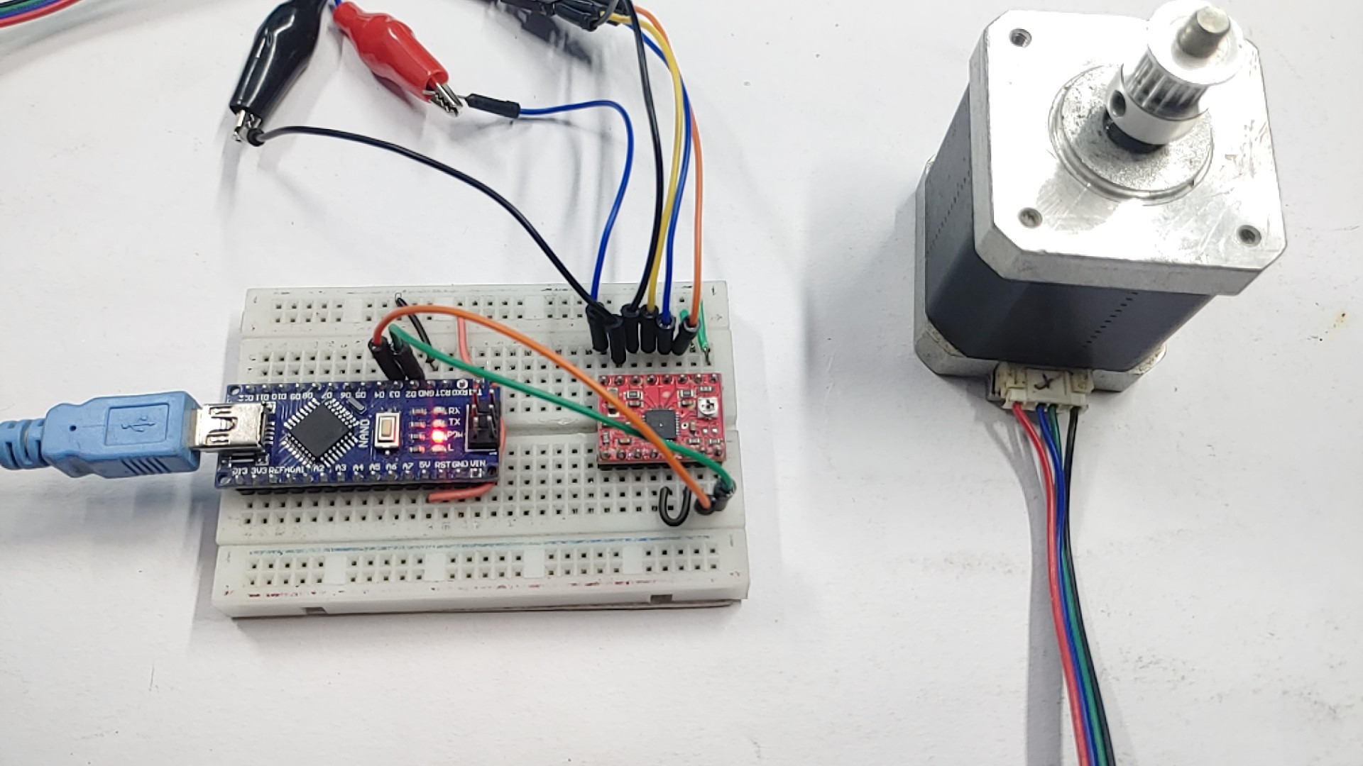
Wiring – Stepper Motor With Arduino & A4988 Driver
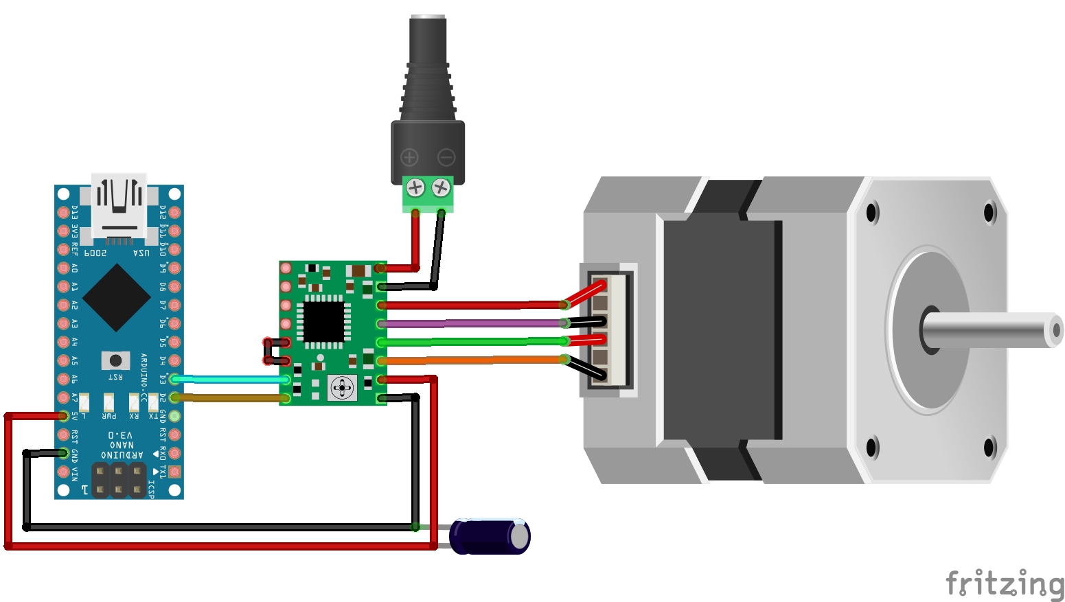
The VMOT pin is powered by a 12V supply, Remember to place a large 100µF decoupling electrolytic capacitor on the motor power pins close to the board.
Here is the pin mapping
- VDD –> Arduino 5V
- GND –> Arduino GND
- VMOT –> Positive terminal power supply
- GND –> Negative terminal power supply
- DIR (Direction) –> Arduino Pin 2
- Step —> Arduino Pin 3
- 2B –> Stepper motor red wire
- 2A –> Stepper motor green wire
- 1A –> Stepper motor yellow wire
- 1B –> Stepper Motor blue wire
You need to connect RST and SLP together, otherwise the driver won’t on.
Example Code
|
1 2 3 4 5 6 7 8 9 10 11 12 13 14 15 16 17 18 19 20 21 22 23 24 25 26 27 28 29 30 31 |
int dirPin =2; int stepperPin = 3; void setup() { pinMode(dirPin, OUTPUT); pinMode(stepperPin, OUTPUT); } void step(boolean dir,int steps) { digitalWrite(dirPin,dir); delay(50); for(int i=0;i<steps;i++) { digitalWrite(stepperPin, HIGH); delayMicroseconds(600);//Adjust the speed of motor. Increase the value, motor speed become slower. digitalWrite(stepperPin, LOW); delayMicroseconds(600); } } void loop() { //steps per revolution for 200 pulses = 360 degree full cycle rotation step(true,1000);//(direction ,steps per revolution). This is clockwise rotation. delay(500); step(false,1000);//Turn (direction ,steps per revolution). This is anticlockwise rotation. delay(500); } |
The stepper motor is connected to the board via two pins: dirPin and stepperPin.
dirPin is used to control the direction of the motor, while stepperPin is used to send pulses to the motor, forcing it to move in steps.
Note – Before connecting the motor power supply to the module, the sample source code must be uploaded first into the Arduino UNO.
Control Stepper Motor Using Potentiometer & A4988 Driver
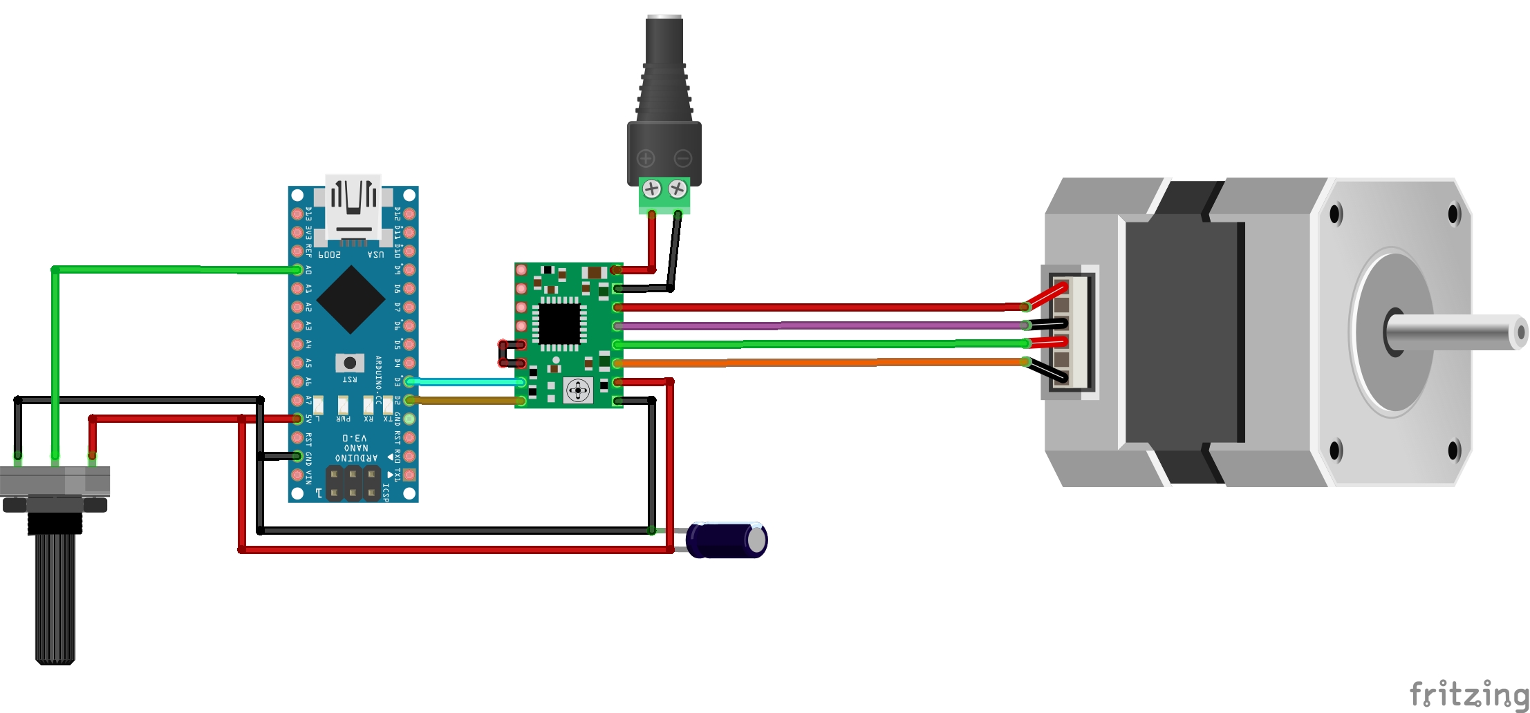
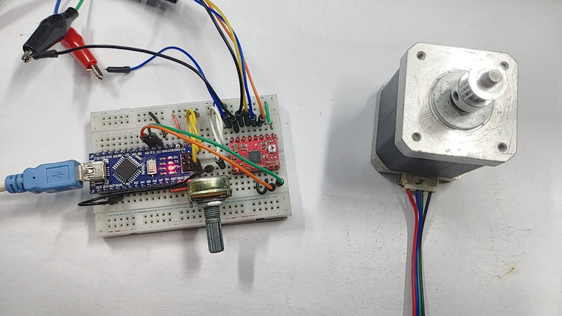
Stepper motors can also be controlled using potentiometers. This article uses a 10K potentiometer and connects it to the analog pin A0 of the Arduino.
The voltage fed into the Arduino analog pins can be used as a reference voltage to control the speed of the stepper motor. The connection diagram is as follows.
Source Code
|
1 2 3 4 5 6 7 8 9 10 11 12 13 14 15 16 17 18 19 20 21 22 23 24 25 26 27 28 29 30 31 32 33 34 35 |
const int stepPin = 3; const int dirPin = 4; const int switchPin = 2; int customDelay, customDelayMapped; void setup() { pinMode(stepPin, OUTPUT); pinMode(dirPin, OUTPUT); pinMode(switchPin, INPUT_PULLUP); // Set the switch pin as an input with a pullup resistor digitalWrite(dirPin, HIGH); // Set the initial direction to clockwise } void loop() { // Check if the switch is pressed and update the direction accordingly if (digitalRead(switchPin) == LOW) { digitalWrite(dirPin, LOW); // Set the direction to counterclockwise } else { digitalWrite(dirPin, HIGH); // Set the direction to clockwise } customDelayMapped = speedUp(); // Get the delay value from the speedUp function // Step the motor with the custom delay and direction digitalWrite(stepPin, HIGH); delayMicroseconds(customDelayMapped); digitalWrite(stepPin, LOW); delayMicroseconds(customDelayMapped); } int speedUp() { int customDelay = analogRead(A0); int newCustom = map(customDelay, 0, 1023, 300, 4000); return newCustom; } |
Copy the code below and upload it to the Arduino Nano.

1 Comment
Pingback: How To Make A Self Solving Rubiks Cube Using Arduino