Introduction
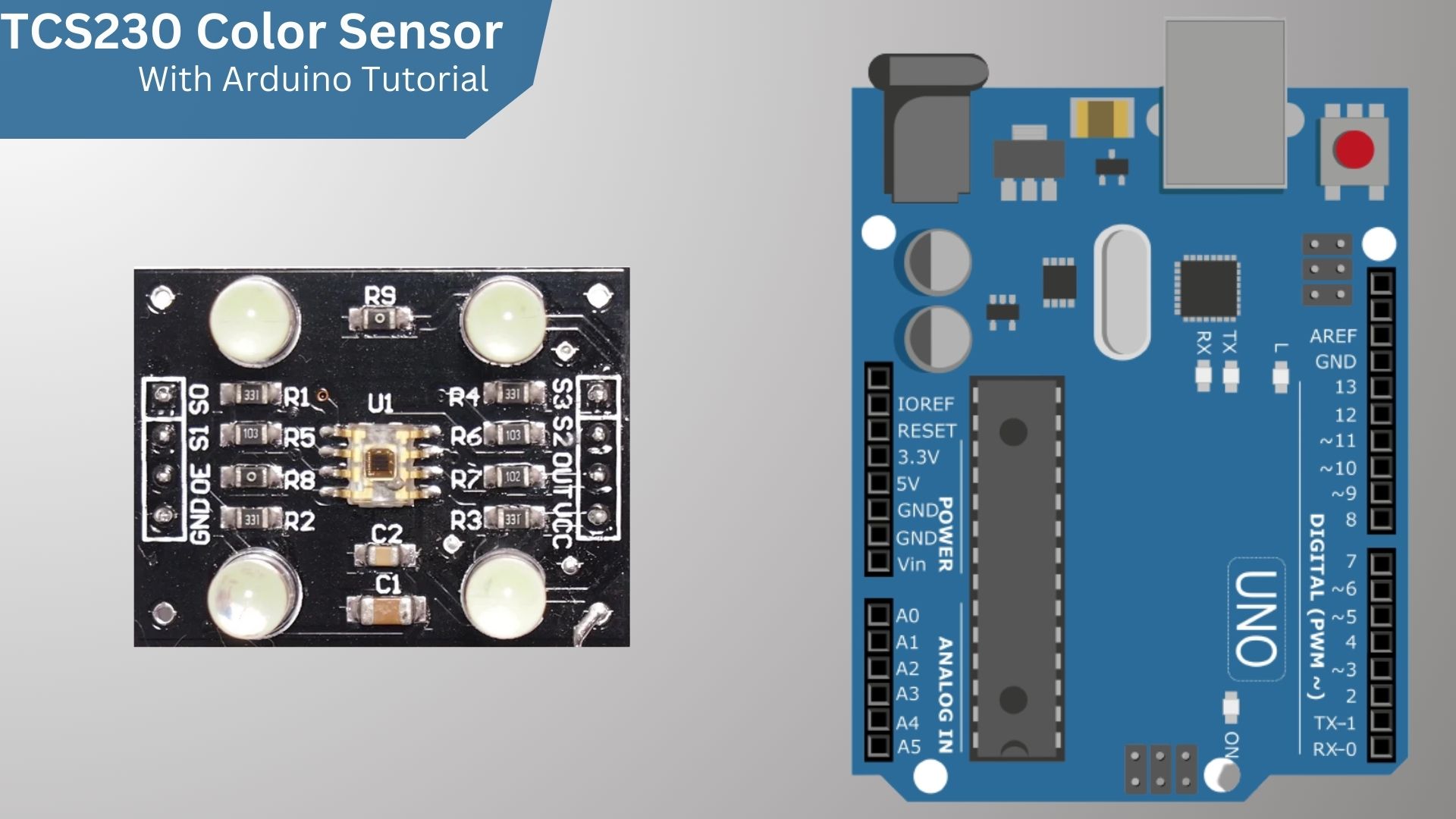
This guide shows you how to use the TCS3200 Color Sensor with Arduino. The TCS3200 can be used to detect the colour of an object. It can also be used to measure the intensity of light.
The TCS3200 color sensor is a fast, easy-to-use, and low-cost color sensor that can be used with an Arduino. The sensor has a built-in red, green, and blue (RGB) LED that can be used to test the color of an object. The sensor can also be used to measure the intensity of light.
List of materials
- Arduino UNO
- TCS3200 Color Sensor
- RGB LED
- Jumper wire
What is the TCS230 Color Sensor?
The TCS230 Color Sensor is a light-to-digital converter that uses a photodiode to sense the intensity of light. The output of the sensor is proportional to the intensity of the light. The sensor has a three-colour LED that is used to illuminate the object being measured. The LED emits red, green, and blue light, and the photodiode measures the intensity of the light. The output of the sensor is a digital signal that is sent to a microcontroller. The microcontroller can be used to calculate the colour of the object being measured. How Color Sensors Work
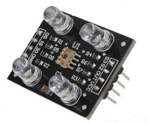
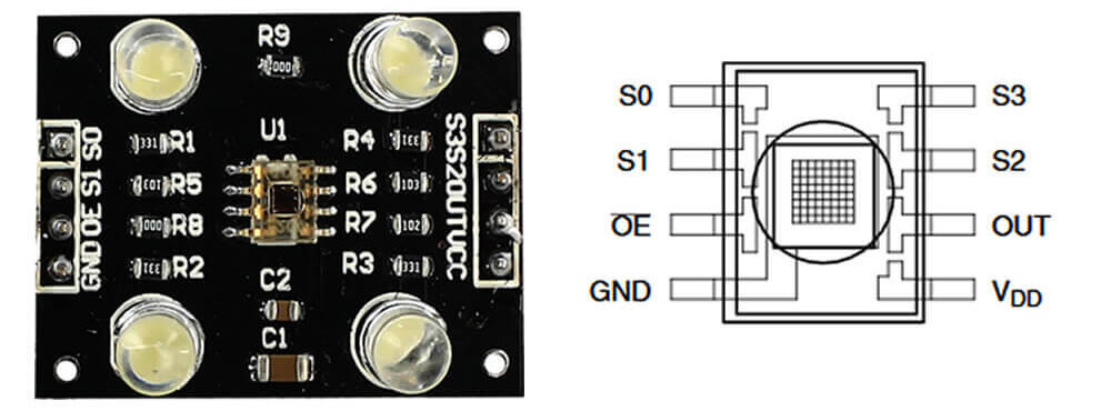
One of the most significant factors for the development of a project is the identification of the pins of our module, therefore, below is a full image of the sensor with the TCS230 Chip in the centre and its respective extensions for installation pins.
The TCS230 color sensor Pinout
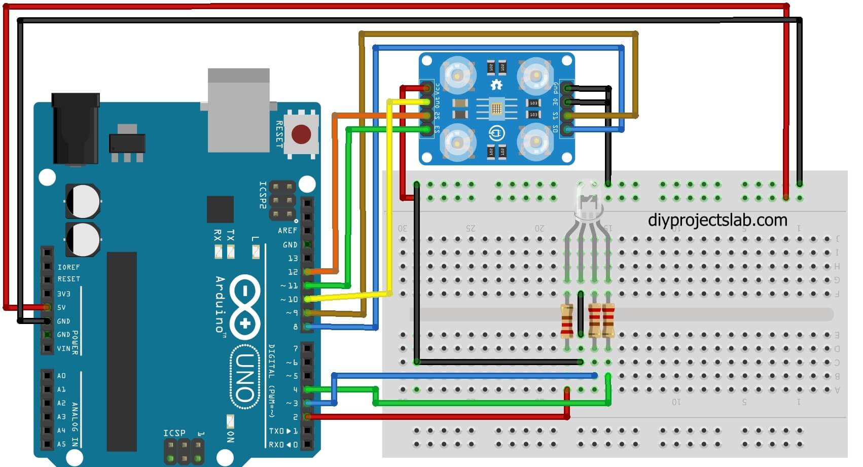
The TCS230 color sensor has two rows of 5 pins, where we find the control pins ( S0 , S1 , S2 , S3 ), output ( OUT ), LED control ( LED ) and power ( VCC and GND ). The Vcc and GND pins are repeated, and you can use either of them to power the module.
Pins S0 and S1 determine the output frequency, and pins S2 and S3 choose which color level will be detected at the moment, according to the table below
| S2 | S3 | Photodiode type |
| LOW | LOW | Red |
| LOW | HIGH | Blue |
| HIGH | LOW | Clear (No filter) |
| HIGH | HIGH | Green |
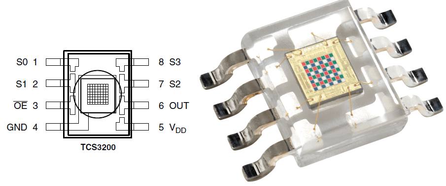
TCS230 chip
The TCS230 chip is a programmable light-to-frequency converter with a square-cond output and a 50% Duty Cycle whose frequency is proportional to light intensity.
Features and Specifications
- Input voltage: (2.7V to 5.5V)
- Interface: Digital TTL
- High-resolution transformation of light intensity to frequency
- Programmable colour and full-scale output frequency
- No need for ADC(Which can be directly connected to the digital pins of the microcontroller)
How to use the TCS230 Color Sensor with Arduino?
In our circuit, we are going to use an Arduino Uno, a TCS3200 color sensor and a RGB LED , which will light up in red, green or blue depending on the color of the object placed in front of the sensor:
Code – TCS3200 Color Sensor With Arduino Program
|
1 2 3 4 5 6 7 8 9 10 11 12 13 14 15 16 17 18 19 20 21 22 23 24 25 26 27 28 29 30 31 32 33 34 35 36 37 38 39 40 41 42 43 44 45 46 47 48 49 50 51 52 53 54 55 56 57 58 59 60 61 62 63 64 65 66 67 68 69 70 71 72 73 74 75 76 77 78 79 80 81 82 83 84 85 86 87 88 89 90 91 92 93 94 95 96 97 98 99 100 101 102 103 104 105 106 107 108 109 110 111 112 113 114 115 116 117 118 119 120 121 122 123 124 125 126 127 128 129 130 131 132 133 134 135 136 137 138 139 140 141 142 143 144 145 146 147 148 149 150 151 152 153 154 155 156 157 158 159 160 161 |
/****************************************************** ********************************* * TCS230 Color Sensor : Identifying Colors (v1.0) The RGB LED will change color according to the color of the object read by the sensor. ****************************************************** *********************************// const int PINO_SENSOR_S0 = 8 ; // BlackBoard pin 8 connected to TCS230 pin S0 const int PINO_SENSOR_S1 = 9 ; // BlackBoard pin 9 connected to TCS230 pin S1 const int PINO_SENSOR_S2 = 11 ; // BlackBoard pin 12 connected to TCS230 pin S2 const int PINO_SENSOR_S3 = 12 ; // BlackBoard pin 11 connected to TCS230 pin S3 const int PINO_SENSOR_OUT = 10 ; // BlackBoard pin 10 connected to the TCS230's OUT pin const int PIN_LED_RED = 2 ; // Pin corresponding to red color const int PIN_LED_GREEN = 3 ; // Pin corresponding to green color const int PIN_LED_BLUE = 4 ; // Pin corresponding to blue color // Variables that store the color value int red = 0 ; int green = 0 ; int blue = 0 ; void setup (){ pinMode ( PINO_SENSOR_S0 , OUTPUT ); // Pin S0 configured as an output pinMode ( PINO_SENSOR_S1 , OUTPUT ); // Pin S1 configured as an output pinMode ( PINO_SENSOR_S2 , OUTPUT ); // Pin S2 configured as an output pinMode ( PINO_SENSOR_S3 , OUTPUT ); // Pin S3 configured as an output pinMode ( PINO_SENSOR_OUT , INPUT ); // OUT pin configured as input pinMode ( PIN_LED_RED , OUTPUT ); // Red RGB pin configured as output pinMode ( PINO_LED_GREEN , OUTPUT ); // Green RGB pin configured as output pinMode ( PINO_LED_BLUE , OUTPUT ); // Blue RGB pin configured as output digitalWrite ( PINO_SENSOR_S0 , HIGH ); // Start the code with pin S0 at high level digitalWrite ( PINO_SENSOR_S1 , LOW ); // Start code with pin S1 at low level } void loop (){ read_colors (); // Call the routine that reads the colors // Check if red color was detected if ( red < blue && red < green ){ digitalWrite ( PIN_LED_RED , HIGH ); // Red at high level digitalWrite ( PINO_LED_GREEN , LOW ); // Green at low level digitalWrite ( PINO_LED_BLUE , LOW ); // Blue at low level } if ( blue < red && blue < green ) { // Check if the blue color was detected digitalWrite ( PIN_LED_RED , LOW ); // Red at low level digitalWrite ( PINO_LED_GREEN , LOW ); // Green at low level digitalWrite ( PINO_LED_BLUE , HIGH ); // Blue at high level } if ( green < red && green < blue ) { // Check if green color was detected digitalWrite ( PIN_LED_RED , LOW ); // Red at low level digitalWrite ( PINO_LED_GREEN , HIGH ); // Green at high level digitalWrite ( PINO_LED_BLUE , LOW ); // Blue at low level } delay ( 100 ); // Wait 100 milliseconds } // Routine that reads the color value void reading_colors (){ digitalWrite ( PINO_SENSOR_S2 , LOW ); // Pin S2 at low level digitalWrite ( PINO_SENSOR_S3 , LOW ); // S3 pin at low level if ( digitalRead ( PINO_SENSOR_OUT ) == HIGH ){ // Check the logic level on the OUT pin of the sensor red = pulseIn ( PINO_SENSOR_OUT , LOW ); // Read pulse duration at the output } else { red = pulseIn ( PINO_SENSOR_OUT , HIGH ); // Read pulse duration at the output } digitalWrite ( PINO_SENSOR_S3 , HIGH ); // PIN S3 at high level if ( digitalRead ( PINO_SENSOR_OUT ) == HIGH ){ // Check the logic level on the OUT pin of the sensor blue = pulseIn ( PINO_SENSOR_OUT , LOW ); // Read pulse duration at the output } else { blue = pulseIn ( PINO_SENSOR_OUT , HIGH ); // Read pulse duration at the output } digitalWrite ( PINO_SENSOR_S2 , HIGH ); // Pin S2 at high level if ( digitalRead ( PINO_SENSOR_OUT ) == HIGH ){ // Check the logic level on the OUT pin of the sensor green = pulseIn ( PINO_SENSOR_OUT , LOW ); // Read pulse duration at the output } else { green = pulseIn ( PINO_SENSOR_OUT , HIGH ); // Read pulse duration at the output } } |
Conclusion
After uploading the code in Arduino ide As you can see, the RGB LED will light up according to the colour of the object in front of the sensor, be it blue, green or red.
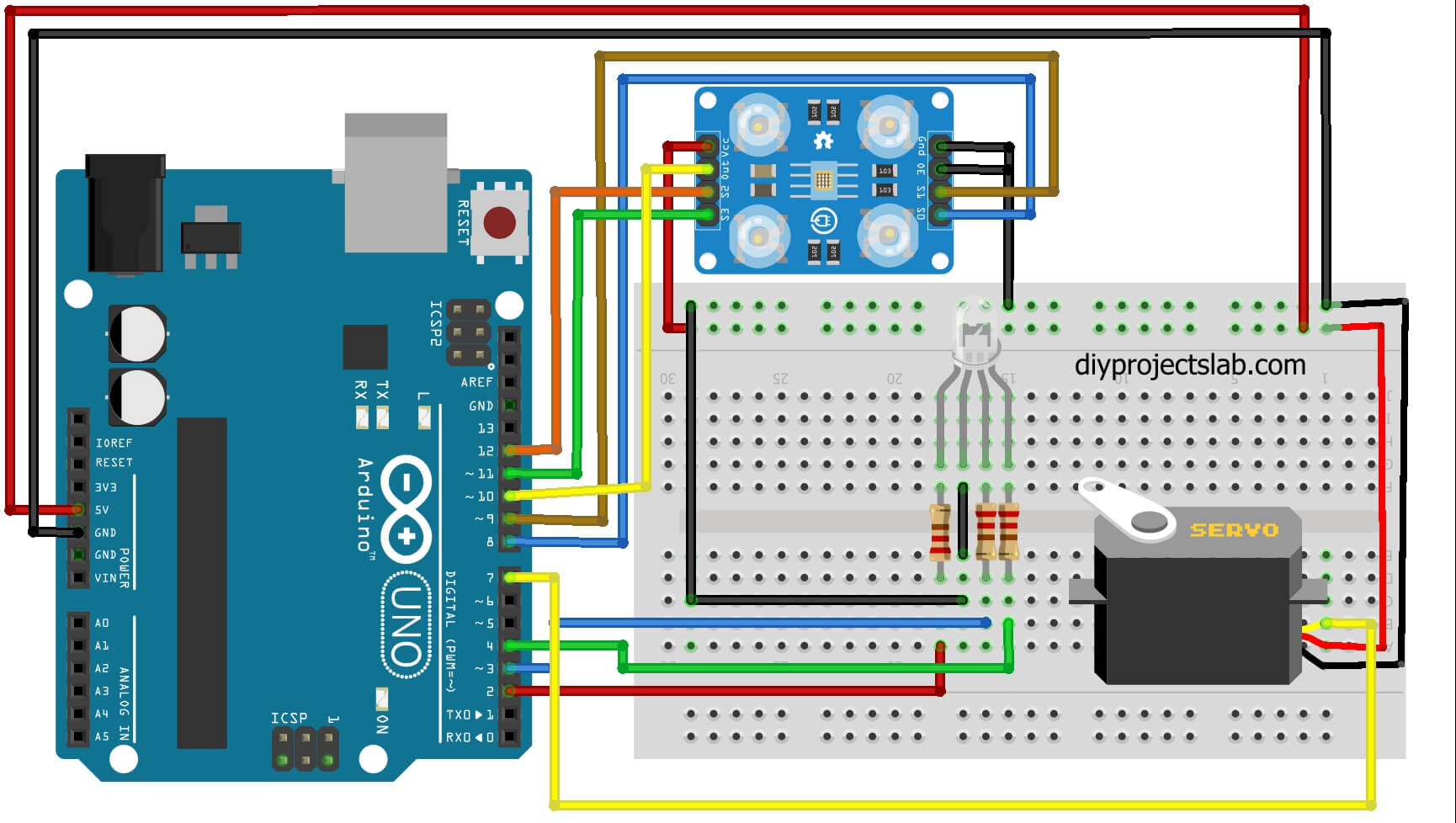
Build the following circuit & Code For Control Servo Motor Using Specific Color
Code-
|
1 2 3 4 5 6 7 8 9 10 11 12 13 14 15 16 17 18 19 20 21 22 23 24 25 26 27 28 29 30 31 32 33 34 35 36 37 38 39 40 41 42 43 44 45 46 47 48 49 50 51 52 53 54 55 56 57 58 59 60 61 62 63 64 65 66 67 68 69 70 71 72 73 74 75 76 77 78 79 80 81 82 83 84 85 86 87 88 89 90 91 92 93 94 95 96 97 98 |
#include <Servo.h> const int PINO_SENSOR_S0 = 8; // BlackBoard pin 8 connected to TCS230 pin S0 const int PINO_SENSOR_S1 = 9; // BlackBoard pin 9 connected to TCS230 pin S1 const int PINO_SENSOR_S2 = 11; // BlackBoard pin 12 connected to TCS230 pin S2 const int PINO_SENSOR_S3 = 12; // BlackBoard pin 11 connected to TCS230 pin S3 const int PINO_SENSOR_OUT = 10; // BlackBoard pin 10 connected to the TCS230's OUT pin const int PIN_LED_RED = 2; // Pin corresponding to red color const int PIN_LED_GREEN = 3; // Pin corresponding to green color const int PIN_LED_BLUE = 4; // Pin corresponding to blue color // Variables that store the color value red int = 0; green int = 0; int blue = 0; Servo servo_motor; // Create an object for servo control void setup(){ pinMode(PINO_SENSOR_S0, OUTPUT); // Pin S0 configured as an output pinMode(PINO_SENSOR_S1, OUTPUT); // Pin S1 configured as an output pinMode(PINO_SENSOR_S2, OUTPUT); // Pin S2 configured as an output pinMode(PINO_SENSOR_S3, OUTPUT); // Pin S3 configured as an output pinMode(PINO_SENSOR_OUT, INPUT); // OUT pin configured as input pinMode(PIN_LED_RED, OUTPUT); // Red RGB pin configured as output pinMode(PIN_LED_GREEN, OUTPUT); // Green RGB pin configured as output pinMode(PIN_LED_BLUE, OUTPUT); // Blue RGB pin configured as output digitalWrite(PINO_SENSOR_S0, HIGH); // S0 pin at high level digitalWrite(PINO_SENSOR_S1, LOW); // Pin S1 at low level servo_motor.attach(6); // Informs which pin will be used for the previously declared servo } void loop(){ read_colors(); // Call the routine that reads the colors servo_motor.write(90); // Tells the servo that it should position itself at 90 degrees // Check if red color was detected if (red < blue && red < green){ digitalWrite(RED_LED_PIN, HIGH); // Red at high level digitalWrite(PIN_LED_GREEN, LOW); // Green at low level digitalWrite(PINO_LED_BLUE, LOW); // Blue at low level } if (blue < red && blue < green) { // Check if blue color was detected digitalWrite(RED_LED_PIN, LOW); // Red at low level digitalWrite(PIN_LED_GREEN, LOW); // Green at low level digitalWrite(PIN_LED_BLUE, HIGH); // Blue at high level servo_motor.write(10); // Tells the servo that it should position itself at 10 degrees } if (green < red && green < blue) { // Check if green color was detected digitalWrite(RED_LED_PIN, LOW); // Red at low level digitalWrite(PIN_LED_GREEN, HIGH); // Green at high level digitalWrite(PINO_LED_BLUE, LOW); // Blue at low level } delay(300); // Wait 100 milliseconds } // Routine that reads the color value void read_colors() { digitalWrite(PINO_SENSOR_S2, LOW); // Pin S2 at low level digitalWrite(PINO_SENSOR_S3, LOW); // S3 pin at low level if(digitalRead(PINO_SENSOR_OUT) == HIGH){ // Check the logic level on the OUT pin of the sensor red = pulseIn(PINO_SENSOR_OUT, LOW); // Read pulse duration at sensor output } else { red = pulseIn(PINO_SENSOR_OUT, HIGH); // Read pulse duration at sensor output } digitalWrite(PINO_SENSOR_S3, HIGH); // PIN S3 at high level if(digitalRead(PINO_SENSOR_OUT) == HIGH){ // Check the logic level on the OUT pin of the sensor blue = pulseIn(PINO_SENSOR_OUT, LOW); // Read pulse duration at sensor output } else { blue = pulseIn(PINO_SENSOR_OUT, HIGH); // Read pulse duration at sensor output } digitalWrite(PINO_SENSOR_S2, HIGH); // Pin S2 at high level if(digitalRead(PINO_SENSOR_OUT) == HIGH){ // Check the logic level on the OUT pin of the sensor green = pulseIn(PINO_SENSOR_OUT, LOW); // Read pulse duration at sensor output } else { green = pulseIn(PINO_SENSOR_OUT, HIGH); // Read pulse duration at sensor output } } |
Conclusion
When recognizing the blue color, the claw closes in order to capture the object in front of it, otherwise, the claw will remain open, as if waiting for a new reading.
- How to Use an LDR Sensor With Arduino Tutorial
- Explain MQ2, MQ3, MQ7 and MQ135 Gas Sensor With Arduino Tutorials
- Tutorial DS1307 RTC Module With Arduino
- Interface HC-SR04 Ultrasonic Sensor With Arduino
- Interface Rotary Encoder With Arduino, How It Works, Codes
- Interface SIM800L with Arduino Tutorial – How It Works, Codes

