In this tutorial, we’ll interface the temperature sensor, DS18B20 Arduino. The DS18B20 is a digital temperature sensor that is used to measure temperature in both Celsius and Fahrenheit. This sensor provides accurate temperature measurements ranging from -55°C to 125°C and can be used in different applications such as weather monitoring, temperature control systems, and industrial automation.
This tutorial shows you how to use the DS18B20 temperature sensor with Arduino, and how to display the temperature on an LCD display.
Required Material
- DS18B20 temperature sensor
- Arduino board
- 4.7kΩ resistor
- Breadboard
- Jumper wires
DS18B20 Waterproof Digital Temperature Sensor
The DS18B20 is a 3-pin digital temperature sensor manufactured by Dallas Semiconductor, sensor uses the 1-Wire protocol to communicate with a microcontroller. It features a high-precision and low-cost sensor that can measure temperatures from -55°C to +125°C with an accuracy of ±0.5°C.

The sensor is normally available in two efficient factors. One comes in a TO-92 package, like a transistor. The other comes in the form of a waterproof stainless steel tube. We can measure temperatures from –55°C to 125°C with a sensor that has a resolution of 9 bits to 12 bits.
Pinout – DS18B20 Waterproof Digital Temperature Sensor
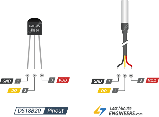
DS18B20 Sensor Features
- Temperature range: The temperature range can measure temperatures from -55°C to +125°C with an accuracy of ±0.5°C.
- Digital output: It communicates with the microcontroller using a 1-wire serial data protocol, which means it requires a single data wire
- Multiple sensors: It supports multiple sensors on a single bus, which means that multiple sensors can be connected to the same data wire.
DS18B20 Sensor Specification
Here are the specifications for the DS18B20 sensor
- Temperature range: -55°C to +125°C
- Temperature accuracy: ±0.5°C (-10°C and +85°C)
- Stainless steel
- Resolution: 9 to 12 bits
- Operating voltage: 3.0V to 5.5V
- Interface: 1-wire interface
- Maximum conversion time: 750ms
- Maximum operating current: 1.5mA
- Maximum standby current: 1µA
- Supports multiple sensors in a single bus
- Package: TO-92, SO-8 or DSBGA
For more information DS18B20 datasheet.
DS18B20 Sensor Block Diagram
DS18B20 Sensor Applications
Here are some common applications of DS18B20 sensor
- Industrial automation
- Thermostat controls
- Environmental measurements
- Consumer products
- Thermometers
- Automotive industry
- Weather stations
- Home automation
- Medical applications
- Agriculture
Powering DS18B20 Sensor
The DS18B20 temperature sensor can be powered in two ways.
- Parasitic Power Mode
- External Power Mode
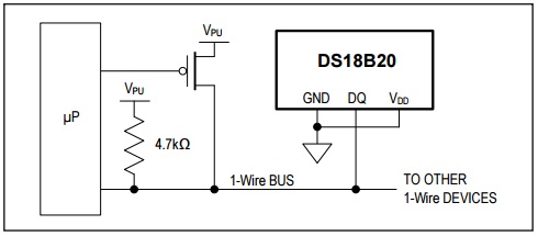
Parasitic Power Mode
In this mode, the DS18B20 is powered through the data line. The power is supplied by the MCU, which sends a strong pull-up signal on the data line. then DS18B20 uses the power from the pull-up signal to operate. This mode requires only two wires, one for data and one for ground.
This way, the sensor internally receives power from the data pin when it is in a high state and charges into the capacitor when the data line is in a low state, this way of receiving power is called “parasite power“.
Generally, this way is used when the sensor needs to be connected over a long distance or where space is limited, as the VDD line is not needed in this way of connecting
Note – GND and VDD pins are both connected to GND, this is essential for the Parasite Power to activate.
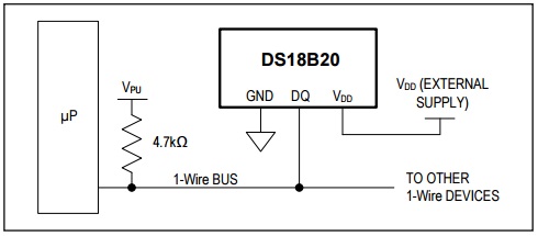
External Power Mode
In this mode, DS18B20 is powered by the external power supply, which is connected by VDD and the ground pins of the sensor. The data line is used to communicate with the microcontroller. This mode requires three wires, one for data, one for VDD, and one for ground.
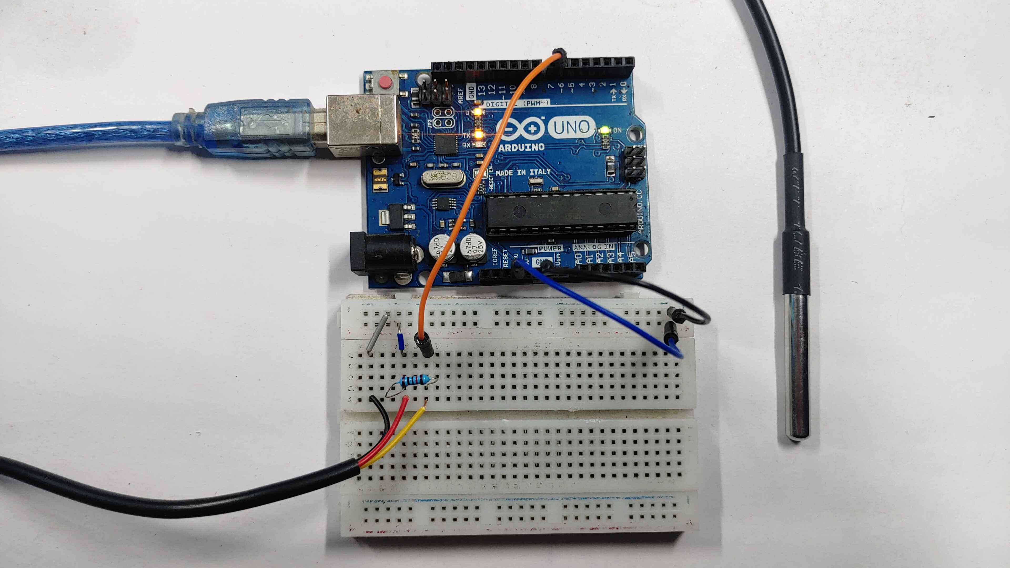
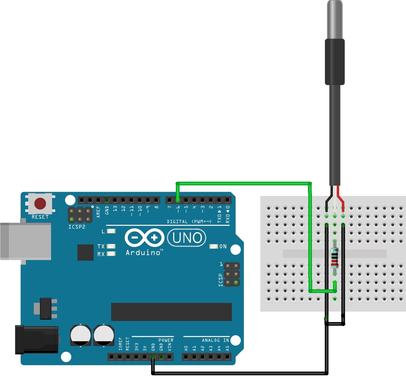
Wiring Diagram – Temperature sensor DS18B20 Arduino
The sensor has three pins: VCC, GND, and DQ (data). Connect VCC to a 3.3V or 5V power supply, GND to ground, and data to D6 pin.
1. External Power Mode
2. Parasitic Power Mode
As I mentioned, it requires a 4.7K pull-up resistor to operate properly. This resistor is connected between the data line of the sensor (Data) and the power supply voltage (VCC).
Code & Libraries
The OneWire and DallasTemperature library provides support for the DS18B20 temperature sensor.
Install Library
Open Arduino IDE and go to Sketch > Include Library > Manage Libraries > Search for the library you want to install.
We will need two libraries to work with the DS18B20 on Arduino.
- OneWire https://github.com/PaulStoffregen/OneWire
- DallasTemperature https://github.com/milesburton/Arduino-Temperature-Control-Library
Example code for temperature Reading
This example code for reading the temperature from DS18B20
|
1 2 3 4 5 6 7 8 9 10 11 12 13 14 15 16 17 18 19 20 |
#include <OneWire.h> #include <DallasTemperature.h> OneWire ourWire(6); // Data wire is plugged into digital pin 6 on the Arduino DallasTemperature sensors(&ourWire); void setup() { delay(1000); Serial.begin(9600); // Start serial communication sensors.begin(); // Initialize the DS18B20 sensor } void loop() { sensors.requestTemperatures(); // Request temperature conversion float temp= sensors.getTempCByIndex(0); //Read temperature in Celsius Serial.print("Temperature= "); Serial.print(temp); Serial.println(" °C"); delay(100); } |
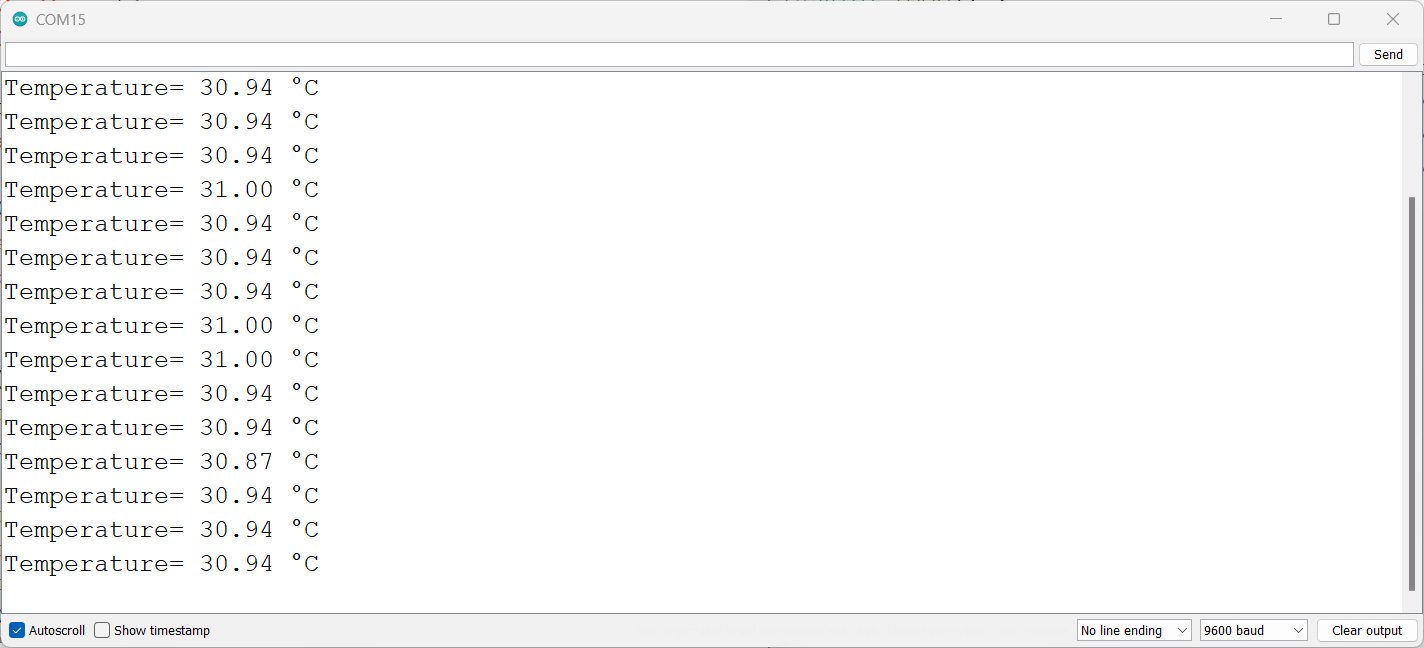
The result is as follows:
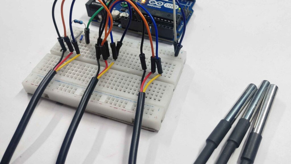
Read Multiple Sensor Temperature
We have two options that can be used when reading more than one temperature sensor.
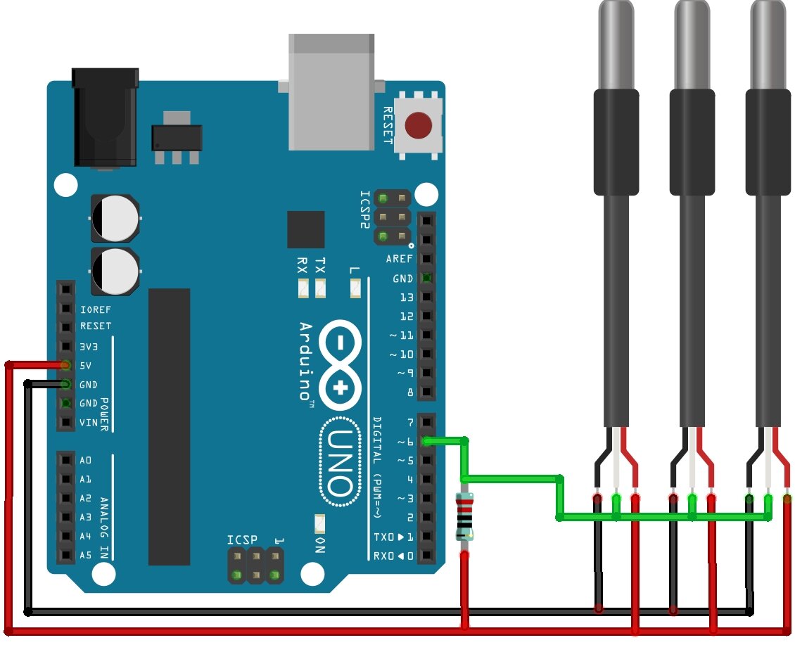
The first method is Each sensor can be connected to an Arduino with a different digital pin.
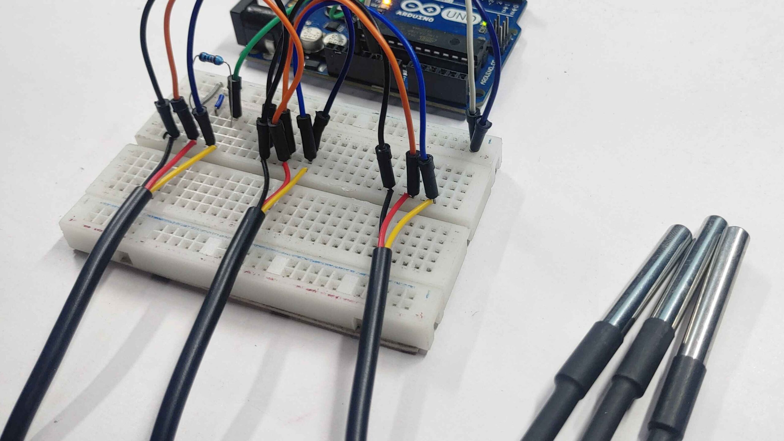
Another way is to use the same pin for all the sensors, in other words, all the sensors are connected to the same 1-Wire bus, and like any bus, each device has its own identification or address. In the case of the DS18B20, we need to find out its address.
Source code For Check I2C Address
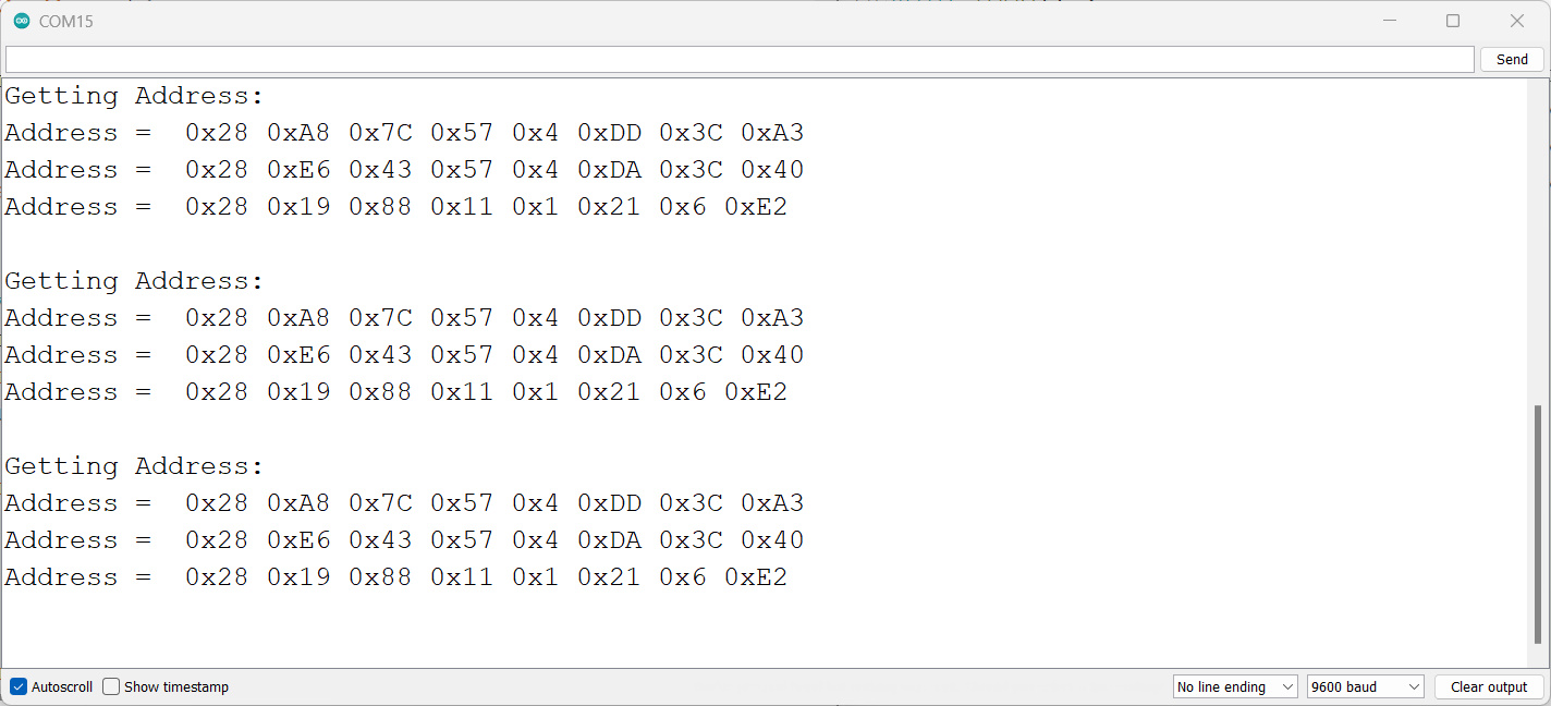
The following code is only used to get the address of each device connected to the 1-wire bus:
|
1 2 3 4 5 6 7 8 9 10 11 12 13 14 15 16 17 18 19 20 21 22 23 24 25 |
#include <OneWire.h> OneWire ourWire(6); //Set up pin 2 as OneWire bus void setup(void) { Serial.begin(9600); } void loop(void) { byte addr[8]; Serial.println("Getting directions:"); while (ourWire.search(addr)) { Serial.print("Address = "); for( int i = 0; i < 8; i++) { Serial.print(" 0x"); Serial.print(addr[i], HEX); } Serial.println(); } Serial.println(); ourWire.reset_search(); delay(2000); } |
Check I2C Address
Main Code
|
1 2 3 4 5 6 7 8 9 10 11 12 13 14 15 16 17 18 19 20 21 22 23 24 25 26 27 28 29 30 31 32 33 34 35 36 |
#include <OneWire.h> #include <DallasTemperature.h> OneWire ourWire(6); DallasTemperature sensors(&ourWire); DeviceAddress address1 = {0x28, 0xA8, 0x7C, 0x57, 0x4, 0xDD, 0x3C, 0xA3};// sensor 1 DeviceAddress address2 = {0x28, 0xE6, 0x43, 0x57, 0x4, 0xDA, 0x3C, 0x40};// sensor 2 DeviceAddress address3 = {0x28, 0x19, 0x88, 0x11, 0x1, 0x21, 0x6, 0xE2};// sensor 3 void setup() { delay(1000); Serial.begin(9600); sensors.begin(); } void loop() { sensors.requestTemperatures(); //send the command to get the temperatures float temp1= sensors.getTempC(address1);//The temperature in °C of sensor 1 is obtained float temp2= sensors.getTempC(address2);//The temperature in °C of sensor 2 is obtained float temp3= sensors.getTempC(address3);//The temperature in °C of sensor 3 is obtained Serial.print("temperature 1 = "); Serial.print(temp1); Serial.print(" C"); Serial.print(" temperature 2 = "); Serial.print(temp2); Serial.print(" C"); Serial.print(" temperature 3 = "); Serial.print(temp3); Serial.println(" C"); delay(100); delay(100); } |
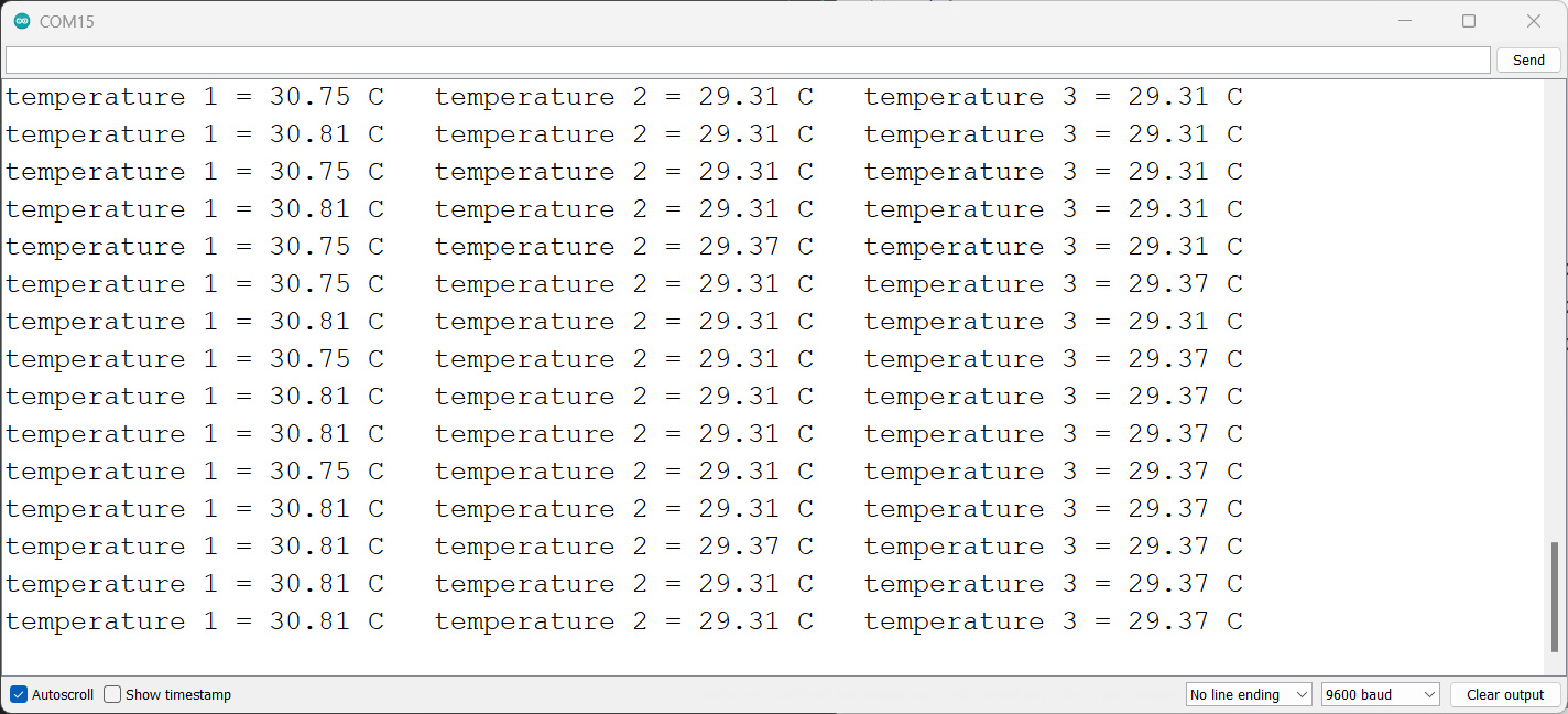
Here we show our results:
The temperatures sensed are similar since the sensors were in the same environment:
|
1 |
sensors.setResolution(Address, 9); // 9-bit resolution |
To change the sensor resolution to 9, 10, 11, or 12 bits, just use the function.
Resolution: The lower the resolution, the less reading time will be.
Working




1 Comment
well done