Summary of Types of 547 Transistors
The 547 transistor family includes a wide range of bipolar junction transistors (BJTs), which are widely used in different electronic applications. These transistors are well known for being reasonably priced, trustworthy, and adaptable. A collection of general-purpose, low-power transistors with the 547 designation often have similar features, while they may vary slightly in other respects.
Common Types of 547 Transistors
547 transistors come in a number of popular variants that are widely used in electrical circuits. A couple of the more well-liked versions are listed below:
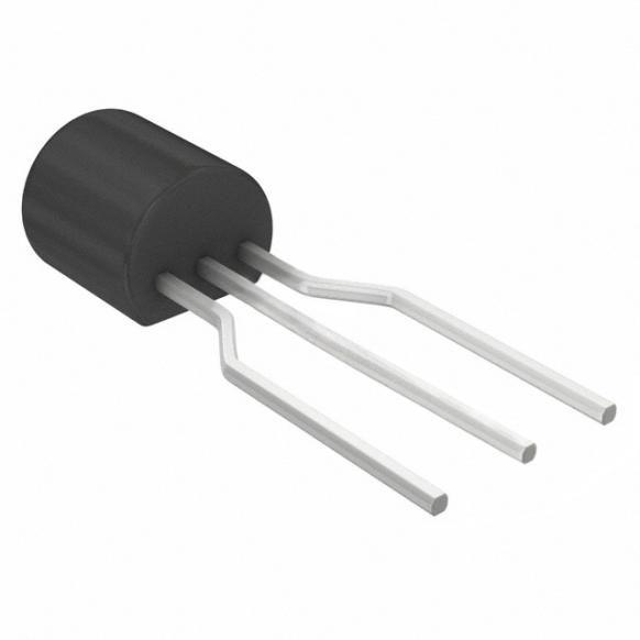
- BC547: The BC547 is a versatile NPN transistor that finds extensive usage in a range of electronic applications. It is renowned for being inexpensive, dependable, and adaptable. Circuits for switching and amplification frequently use the BC547.
- BC548: The BC548 and BC547 are nearly identical, with a few minor variations in their specs. It frequently replaces the BC547 in a variety of applications.
- BC549: Another member of the same family, the BC549 has somewhat different specs and is best suited for low-noise applications.
- 2N3904: Although it is not a “547” type, the 2N3904 is a widely used NPN transistor that is frequently utilized in applications that are comparable to those of the BC547.
- BC337: Occasionally utilized as a substitute in circuits needing greater power, this transistor has a little higher current handling capacity than the BC547.
These widely used 547 transistor types have a wide range of applications in electrical design. Each sort can be employed for certain circuit requirements because of its unique characteristics and specifications.
When selecting a transistor for a particular application, it is essential to consider factors including voltage and current ratings, gain, frequency responsiveness, and noise performance to ensure optimal circuit operation.
What is BC547 Transistor?
The BC547 transistor, which has a gain value that can vary from 110 to 800, is crucial for signal amplification. By displaying the amount that the transistor can amplify an input signal, this gain value draws attention to its amplification capabilities. It is crucial to keep in mind that the maximum current capability of the Collector pin is 100mA. In order to ensure proper functioning and prevent any damage, all connected loads must not exceed this threshold.
To correctly bias the transistor, a current of no more than 5 mA must reach the base pin, identified as IB. Biasing is a crucial step in the process that guarantees a transistor operates within its specified parameters.
The BC547 functions by allowing a moderate base current to control a higher collector-emitter current. This makes it an excellent option for a range of electrical circuits, including amplifiers and switches. The transistor can be used in common emitter, common base, or common collector topologies, depending on the requirements of the application.
The BC547 is available in three different variations: BC547A, BC547B, and BC547C. Their current gain (hFE) is the primary distinction between them. The variation with the most increase is the ‘C‘ variety, whereas the one with the lowest is the ‘A‘ variant. The specific gain needs of a user’s circuit often dictate which version they choose.
Octopart is a comprehensive platform that offers users a single point of contact for all of their electrical component needs by compiling data from hundreds of manufacturers and distributors around the globe. You can find all kinds of transistors from this platform.
Operational Status of BC547 Transistor
Similar to other transistors, the BC547 operates in three regions: the Amplification Region, Saturation Region, and Cutoff Region. The BC547 transistor’s three operating areas are as follows:
Region of Amplification:
- The amplification region is located between the saturation and cutoff regions. In this active region, the transistor’s emitter junction is forward biased and its collector junction is reverse biased. Here, the collector current is equal to β times the base current, or IC = β IB, where β is the current gain factor, IB is the base current, and IC is the collector current.
Region of Saturation:
- Here, the transistor serves as a short circuit. Both the collector and emitter currents are maximum. In the saturation zone, there is forward bias at both the emitter and collector junctions. In other words, IC equals IE, where IE is the emitter current and IC is the collector current. This indicates that the transistor operates as the highest current-carrying short circuit or closed switch.
Region of Cutoff:
- In this sense, the transistor operates as an open switch or open circuit. The emitter, collector, and base are all devoid of current. In the cutoff area, there is reverse bias at both the emitter and collector junctions. The following can be written for it: The formula is IC = IE = IB = 0, where IE denotes emitter current, IB denotes base current, and IC stands for collector current. This is a result of the base, emitter, and collector currents being zero in this area.
Principle of operation of the BC547 transistor
The Transistor’s Bias: The BC547 is operated by applying a little current to its base (IB). This current regulates a larger current that travels from the collector (IC) to the emitter (IE). The relationship between these currents is defined by the transistor’s current gain (hFE), which indicates how much the base current is amplified. For example, if hFE is 100 and IB is 1 mA, then IC can be as high as 100 mA.
Current Flow:
- When a positive voltage is applied to the base, electrons can flow from the emitter into the base, creating a forward-biased base-emitter junction. Several of these electrons diffuse past the thin base and into the collector, causing a larger current (IC) to flow from the collector to the emitter.
Saturation and Cut-off:
- Saturation: When the base current is sufficient, the transistor approaches saturation, allowing the maximum amount of current to pass from the collector to the emitter. In this state, the transistor operates like a closed switch.
- Cut-off: When the base current is reduced to zero, the transistor operates like an open switch and stops conducting.
Why does the BC547 Transistor Get Used in the Water Level Indicator?
Water level indication circuits commonly use the BC547 transistor because of its features that make it perfect for switching applications and simple sensor designs. In order to detect whether or not there is water present at different levels, the BC547 is commonly employed as a switch in a water level indicator circuit.
Capacity to Change:
- The BC547 can act as a switch, alternating between the saturation and cut-off zones, depending on the input signal at its base. A water level indicator uses the presence or absence of water at different levels to turn a transistor “on” or “off,” effectively acting as a switch.
Low Power Requirement:
- As a low-power transistor, the BC547 can be utilized in scenarios where power consumption is a concern. For portable gadgets to perform effectively and have a longer battery life, water level monitors with low power consumption are desirable.
Usability:
- BC547 is a good choice for simple electrical applications like water level indicators because it is inexpensive and easily available. Its widespread use in educational and hobbyist projects contributes to its appeal.
Adaptability:
- The BC547 is easy to configure in a range of circuit layouts. A simple switching circuit that activates an indicator (such an LED) when water reaches a certain level can include the transistor found in water level indicators.
Dependableness:
- BC547 transistors are well known for their stability and dependability in switching applications. Given the importance of precise water level detection, this is relevant to water level indicators.
- At different places in the circuit for the water level indicator, the base of the transistor makes contact with the water, completing the circuit and allowing current to flow from the base to the emitter. This current flow shows the presence of water at a specific level by activating the matching segment of the indicator circuit.
BC547 Transistor Applications
Switching Applications
- LED Driving: By passing a tiny current to the base of the BC547, LEDs can be turned on or off. This makes it possible for logic circuits or microcontrollers to regulate high-current loads.
- Relay Driving: By turning the relay coil current on and off, the BC547 is able to drive relays. Usually, a diode is positioned across the relay coil to guard against inductive kickback on the transistor.
Amplification Applications
- Audio Amplifiers: The BC547 can be utilized in audio circuits, such as guitar amplifiers or microphone preamps, as a small-signal amplifier.
- Darlington Pair: To build a high-gain amplifier for driving motors or other high-current loads, two BC547 transistors can be coupled in a Darlington configuration.
Logic Gates
- NAND Gates: By joining several transistors in series, the BC547 can be used to build NAND logic gates. Only when all inputs are low, which turns off every transistor, is the output high.
- NOR Gates: Similarly, BC547 transistors can be connected in parallel to create NOR gates. Only in cases where all inputs are low is the output high.
Sensor Interfacing
- Light Sensors: A basic circuit for a darkness detector can be built using the BC547 and a light-dependent resistor (LDR). The resistance of the LDR varies with light intensity, regulating the BC547’s base current and turning on and off an LED.
- Temperature Sensors: A temperature sensor circuit can be built using the BC547 and a thermistor. Temperature-dependent variations in the thermistor’s resistance have an impact on the BC547’s base current and collector-emitter voltage.
Biasing and Buffering
- Voltage Dividers: To create a steady output voltage that can power other circuits without taxing the input, voltage divider circuits can employ the BC547 as a buffer.
- Emitter Followers: The BC547 can be set up to function as an emitter follower, which produces an output with a low impedance that tracks the input voltage. This is helpful for supplying a steady reference voltage or driving capacitive loads.
BC547 NPN Transistor equivalent
A well-liked NPN bipolar junction transistor with a broad range of electronic applications is the BC547. Nonetheless, in many circuits, a number of transistors can function as BC547 counterparts or substitutes.
The BC548 is one of the most popular substitutes since it has a lot of the same features and is frequently a direct replacement. Another near relative that is great for low-noise applications is the BC549.
Going outside of the BC series, the 2N3904 is a commonly accepted replacement for the BC547. There are a lot of performance and specification similarities with this transistor, which is built in the United States. Another well-liked NPN transistor that frequently works in place of the BC547 is the 2N2222, but it can typically withstand a little bit more current and has a higher gain.
Applications that need to handle slightly more power might give the BC337 more thought. It’s frequently employed in circuits where the BC547’s current capacity could be insufficient, even though it’s not an identical counterpart. Though less prevalent worldwide, the BF494 is occasionally considered a substitute in European circuits.
It’s crucial to remember that although these transistors can be used interchangeably in many situations, there might be a small variance in certain aspects like gain, maximum voltage ratings, or noise characteristics. To ensure compatibility, it is essential to compare the precise characteristics of the replacement transistor and review the circuit’s unique needs when replacing transistors.
Comparison of BC547 Transistor vs 2N2222 Transistor
Well-known NPN BJTs that are frequently utilized in switching and amplification circuits include the BC547 and 2N2222 transistors. Despite their similarities, the 2N2222 performs better in circuits that require a larger current, while the BC547 is better suited for low-power applications.
The exact needs of your project will determine which option is best, especially with regard to gain, power dissipation, and current handling.


