In this tutorial, I will show you how to interface Ultrasonic Distance Sensor With Raspberry Pi Pico. The HC-SR04 ultrasonic distance sensor is an excellent addition to any Raspberry Pi Pico-based project. This sensor can be used to measure the distance between the sensor and an object and can be used in projects such as detecting when someone is close to the sensor or measuring the height of an object.
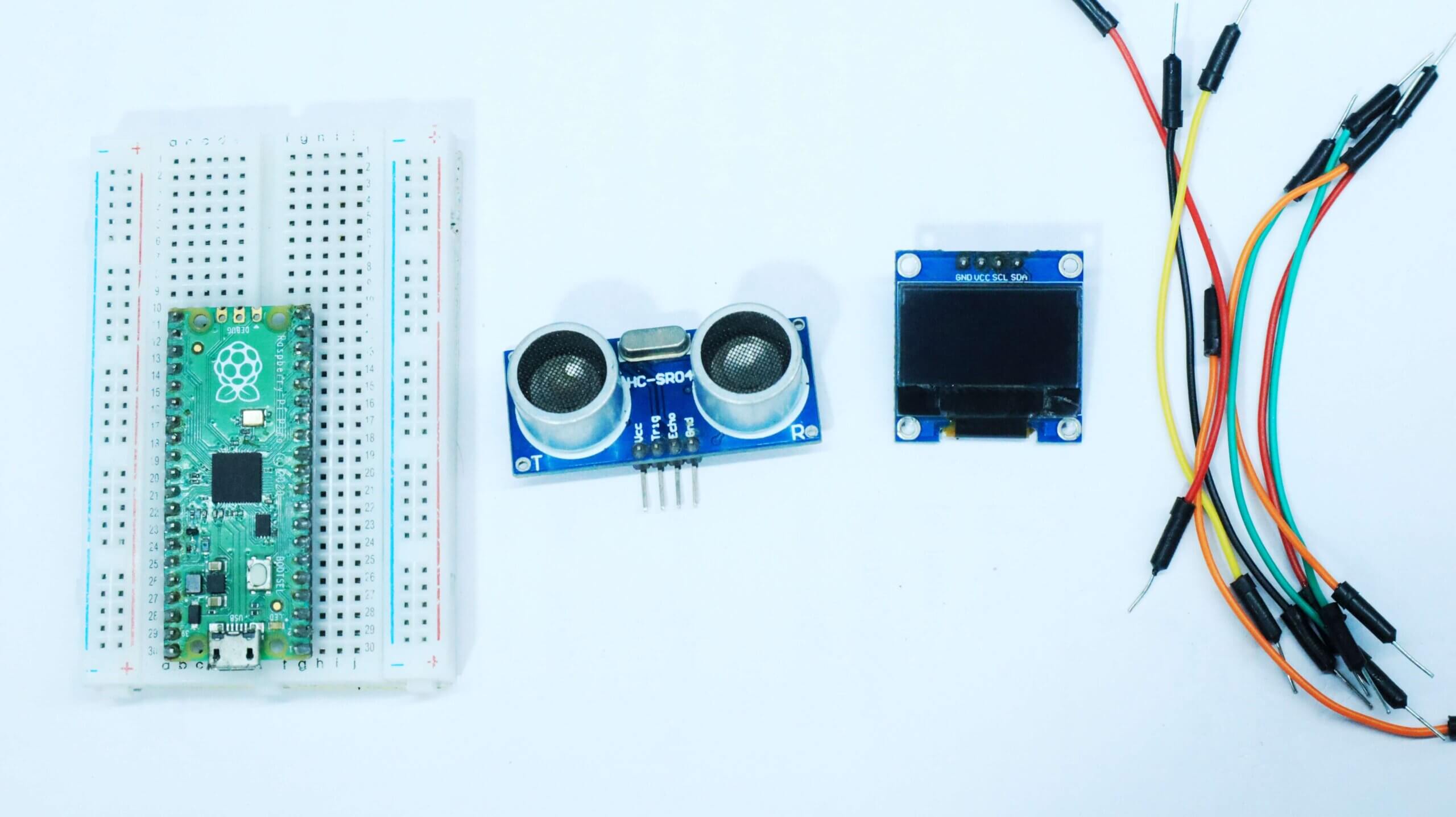
Components
- Raspberry Pi Pico
- USB cable
- HC- SR04 Ultrasonic Sensor
- OLED DISPLAY
- jumper wires
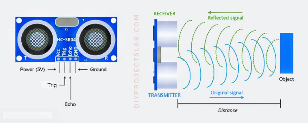
What is Ultrasonic Sensor?
An ultrasonic sensor is a device that uses sound waves to measure distance. It works by sending out a sound wave and then measuring how long it takes for the wave to bounce back. The sensor can then use this information to calculate the distance to the object. Ultrasonic sensors are used in a variety of applications, including automotive safety systems, security systems, and industrial automation.
What is Raspberry Pi Pico ?
The Raspberry Pi Pico is a microcontroller board based on the RP2040 chip developed by Raspberry Pi. It was announced in January 2021. The Pico is similar to other microcontroller boards, such as the Arduino, but it has a unique feature: it can be programmed using the Python programming language. This makes it a great board for beginners who want to learn to program in Python.
The Pico is a great board for projects that need a small, inexpensive microcontroller. It is also a great board for learning to program in Python.
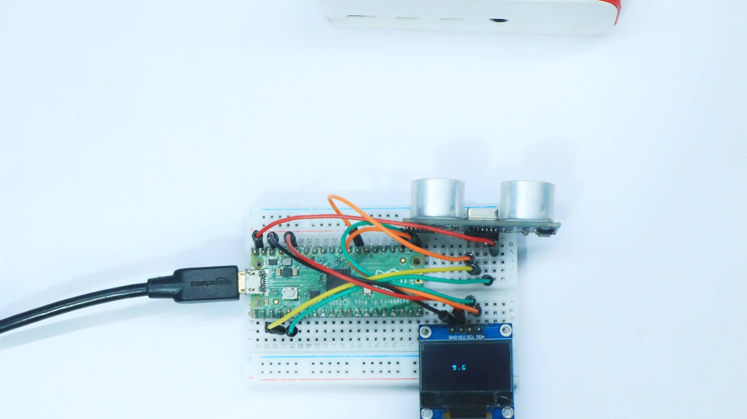
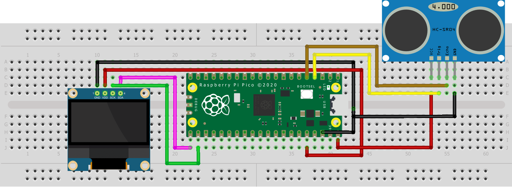
Schematic diagram – Ultrasonic Distance Sensor With Raspberry Pi Pico
The most common way is to use the Raspberrypi pico board and an ultrasonic sensor module. The module has three pins: VCC, GND, and Echo.
The SSD1306 Oled display module connections with Raspberry Pi Pico SCL and SDA pins of the SSD1306 Oled Display module are connected with GP17 and GP16 pins of the Pico Board.
- The VCC pin is connected with the VBus which is Pin40 of the Raspberry Pi Pico.
- The trigger pin is connected with GP3.
- The echo pin is connected with GP2
- The GND pin of the ultrasonic sensor is connected with the GND pin of the Raspberry Pi Pico board.
Programming – Ultrasonic Distance Sensor With Raspberry Pi Pico
ssd1306.py
|
1 2 3 4 5 6 7 8 9 10 11 12 13 14 15 16 17 18 19 20 21 22 23 24 25 26 27 28 29 30 31 32 33 34 35 36 37 38 39 40 41 42 43 44 45 46 47 48 49 50 51 52 53 54 55 56 57 58 59 60 61 62 63 64 65 66 67 68 69 70 71 72 73 74 75 76 77 78 79 80 81 82 83 84 85 86 87 88 89 90 91 92 93 94 95 96 97 98 99 100 101 102 103 104 105 106 107 108 109 110 111 112 113 114 115 116 117 118 119 120 121 122 123 124 125 126 127 128 129 130 131 132 133 134 135 136 137 138 139 140 141 142 143 144 145 146 147 148 149 150 151 152 153 154 155 156 157 158 159 160 161 162 163 |
# MicroPython SSD1306 OLED driver, I2C and SPI interfaces from micropython import const import framebuf # register definitions SET_CONTRAST = const(0x81) SET_ENTIRE_ON = const(0xA4) SET_NORM_INV = const(0xA6) SET_DISP = const(0xAE) SET_MEM_ADDR = const(0x20) SET_COL_ADDR = const(0x21) SET_PAGE_ADDR = const(0x22) SET_DISP_START_LINE = const(0x40) SET_SEG_REMAP = const(0xA0) SET_MUX_RATIO = const(0xA8) SET_IREF_SELECT = const(0xAD) SET_COM_OUT_DIR = const(0xC0) SET_DISP_OFFSET = const(0xD3) SET_COM_PIN_CFG = const(0xDA) SET_DISP_CLK_DIV = const(0xD5) SET_PRECHARGE = const(0xD9) SET_VCOM_DESEL = const(0xDB) SET_CHARGE_PUMP = const(0x8D) # Subclassing FrameBuffer provides support for graphics primitives # http://docs.micropython.org/en/latest/pyboard/library/framebuf.html class SSD1306(framebuf.FrameBuffer): def __init__(self, width, height, external_vcc): self.width = width self.height = height self.external_vcc = external_vcc self.pages = self.height // 8 self.buffer = bytearray(self.pages * self.width) super().__init__(self.buffer, self.width, self.height, framebuf.MONO_VLSB) self.init_display() def init_display(self): for cmd in ( SET_DISP, # display off # address setting SET_MEM_ADDR, 0x00, # horizontal # resolution and layout SET_DISP_START_LINE, # start at line 0 SET_SEG_REMAP | 0x01, # column addr 127 mapped to SEG0 SET_MUX_RATIO, self.height - 1, SET_COM_OUT_DIR | 0x08, # scan from COM[N] to COM0 SET_DISP_OFFSET, 0x00, SET_COM_PIN_CFG, 0x02 if self.width > 2 * self.height else 0x12, # timing and driving scheme SET_DISP_CLK_DIV, 0x80, SET_PRECHARGE, 0x22 if self.external_vcc else 0xF1, SET_VCOM_DESEL, 0x30, # 0.83*Vcc # display SET_CONTRAST, 0xFF, # maximum SET_ENTIRE_ON, # output follows RAM contents SET_NORM_INV, # not inverted SET_IREF_SELECT, 0x30, # enable internal IREF during display on # charge pump SET_CHARGE_PUMP, 0x10 if self.external_vcc else 0x14, SET_DISP | 0x01, # display on ): # on self.write_cmd(cmd) self.fill(0) self.show() def poweroff(self): self.write_cmd(SET_DISP) def poweron(self): self.write_cmd(SET_DISP | 0x01) def contrast(self, contrast): self.write_cmd(SET_CONTRAST) self.write_cmd(contrast) def invert(self, invert): self.write_cmd(SET_NORM_INV | (invert & 1)) def rotate(self, rotate): self.write_cmd(SET_COM_OUT_DIR | ((rotate & 1) << 3)) self.write_cmd(SET_SEG_REMAP | (rotate & 1)) def show(self): x0 = 0 x1 = self.width - 1 if self.width != 128: # narrow displays use centred columns col_offset = (128 - self.width) // 2 x0 += col_offset x1 += col_offset self.write_cmd(SET_COL_ADDR) self.write_cmd(x0) self.write_cmd(x1) self.write_cmd(SET_PAGE_ADDR) self.write_cmd(0) self.write_cmd(self.pages - 1) self.write_data(self.buffer) class SSD1306_I2C(SSD1306): def __init__(self, width, height, i2c, addr=0x3C, external_vcc=False): self.i2c = i2c self.addr = addr self.temp = bytearray(2) self.write_list = [b"\x40", None] # Co=0, D/C#=1 super().__init__(width, height, external_vcc) def write_cmd(self, cmd): self.temp[0] = 0x80 # Co=1, D/C#=0 self.temp[1] = cmd self.i2c.writeto(self.addr, self.temp) def write_data(self, buf): self.write_list[1] = buf self.i2c.writevto(self.addr, self.write_list) class SSD1306_SPI(SSD1306): def __init__(self, width, height, spi, dc, res, cs, external_vcc=False): self.rate = 10 * 1024 * 1024 dc.init(dc.OUT, value=0) res.init(res.OUT, value=0) cs.init(cs.OUT, value=1) self.spi = spi self.dc = dc self.res = res self.cs = cs import time self.res(1) time.sleep_ms(1) self.res(0) time.sleep_ms(10) self.res(1) super().__init__(width, height, external_vcc) def write_cmd(self, cmd): self.spi.init(baudrate=self.rate, polarity=0, phase=0) self.cs(1) self.dc(0) self.cs(0) self.spi.write(bytearray([cmd])) self.cs(1) def write_data(self, buf): self.spi.init(baudrate=self.rate, polarity=0, phase=0) self.cs(1) self.dc(1) self.cs(0) self.spi.write(buf) self.cs(1) |
ultrasonic.py
|
1 2 3 4 5 6 7 8 9 10 11 12 13 14 15 16 17 18 19 20 21 22 23 24 25 26 27 28 29 30 31 32 33 34 35 36 37 38 39 40 41 42 43 44 |
from machine import Pin, I2C from ssd1306 import SSD1306_I2C import utime WIDTH = 128 HEIGHT = 64 i2c = I2C(0, scl = Pin(17), sda = Pin(16), freq=400000) display = SSD1306_I2C(WIDTH, HEIGHT, i2c) trigger = Pin(3, Pin.OUT) echo = Pin(2, Pin.IN) def ultra(): trigger.low() utime.sleep_us(2) trigger.high() utime.sleep_us(5) trigger.low() while echo.value() == 0: signaloff = utime.ticks_us() while echo.value() == 1: signalon = utime.ticks_us() timepassed = signalon - signaloff distance = (timepassed * 0.0343) / 2 distance = "{:.1f}".format(distance) print(distance + " cm") return str(distance) print("fok") ngf = ultra() print(ngf) while True: display.text(ultra(),0,0) display.show() display.fill(0) utime.sleep(1) |
Conclusion
After the Upload code, You will see that the OLED Start Reading on Display.
Read Similar Articles:
- Getting Started Raspberry Pi Pico – Pinout, Specs – Beginner Guide
- Interfacing PIR Motion Sensor with Raspberry Pi Pico
- Raspberry Pi Pico Home Automation System
- Interface Servo Motor With Raspberry Pi Pico
- Interface 0.96″ OLED Display with Raspberry Pi Pico
- Raspberry Pi Pico Weather Station Using Dht11 Sensor
- Interface 16*2 LCD Display With Raspberry Pi Pico


2 Comments
Pingback: Raspberry Pi Pico ADC | Read Analog Values With Micropython
Pingback: Raspberry Pi Pico Projects For Beginners [2022]