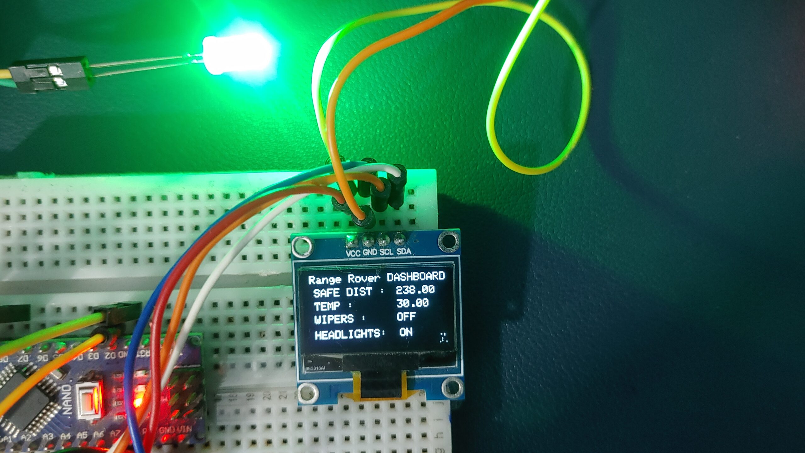
In modern automotive systems, onboard diagnostics (OBD) and efficient data communication between electronic components are essential. Vehicles often rely on the CAN (Controller Area Network) protocol, which enables real-time communication between different parts of the car, enabling effective Monitoring and system management.
This post uses Arduino and the MCP2515 CAN Bus module to receive vehicle data, understand CAN communication, and see its real-world application in automotive diagnostics. check out our previous post How To Use MCP2515 SPI CAN Bus Module with Arduino
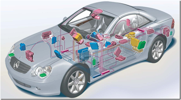
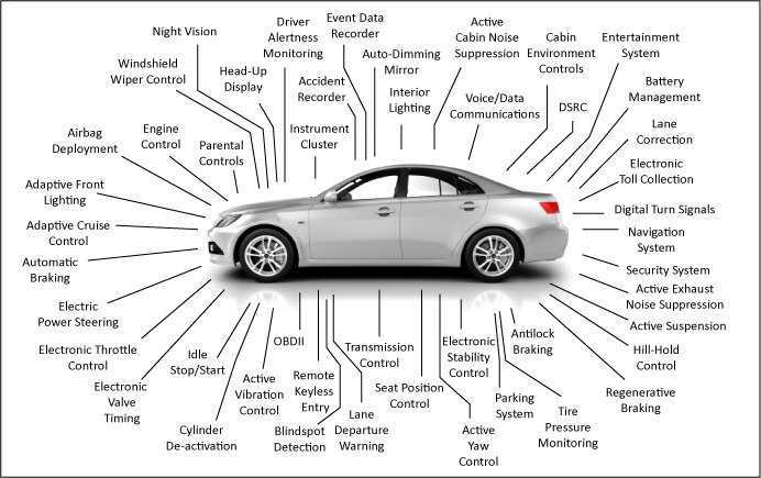
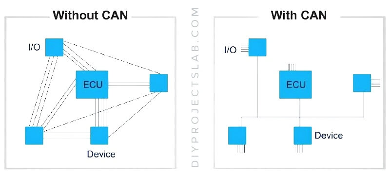
Modern cars have many electronic systems that need to communicate with each other. Instead of having a separate wire for each signal between systems, the CAN-BUS allows different systems (like the engine, brakes, and air conditioning) to share information using fewer wires, making the wiring simpler.
Thank you, PCBWay!
This project was possible thanks to PCBWay’s support. For quality prototype PCBs at great prices, visit their site and get rewards or a free coupon on your first order.
What is CAN Bus, and why is it used?
CAN, short for Controller Area Network, is a serial communication protocol designed for robust and efficient data exchange across vehicle systems. Unlike UART, I2C, or SPI, the Arduino Uno or Nano has no built-in CAN Bus, so we need additional hardware like the MCP2515 CAN Bus module to communicate over CAN.
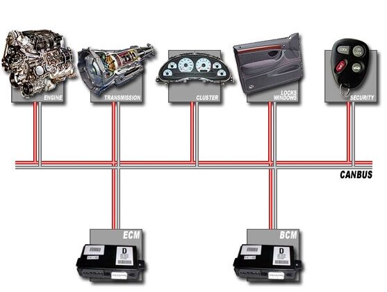
As a network, CAN Bus connects multiple devices, including sensors and actuators, allowing them to share information without needing direct links to a central controller. The CAN Bus is commonly used in the automobile industry because of its reliability, low wiring requirements, and noise protection—perfect for a complex system like a vehicle.
Advantages of CAN
Understanding CAN Communication in Vehicles
In a car, CAN communication is essential for connecting multiple modules, from temperature and tyre pressure sensors to main displays and radar sensors. This communication happens over two lines:
- CAN H (high)
- CAN L (low)
The CAN Bus topology is because it doesn’t require a host or “master.” Each device on the network has equal access and can send messages containing an ID and data payload. Devices receive messages simultaneously but only respond if the message ID matches theirs.
Components Required
To set up a vehicle diagnostic system with Arduino, you’ll need:
- Arduino Board
- MCP2515 CAN Bus Module
- Rain Sensor
- Ultrasonic Sensor
- Temperature Sensor (DHT11)
LDR Sensor - OLED
- Servo Motor
- Fan
- LED
- Jumper Wires
- Breadboard
MCP2515 CAN Bus Module
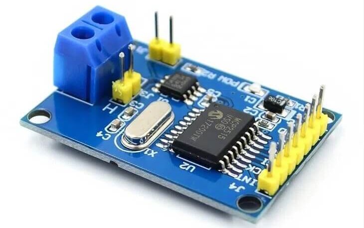
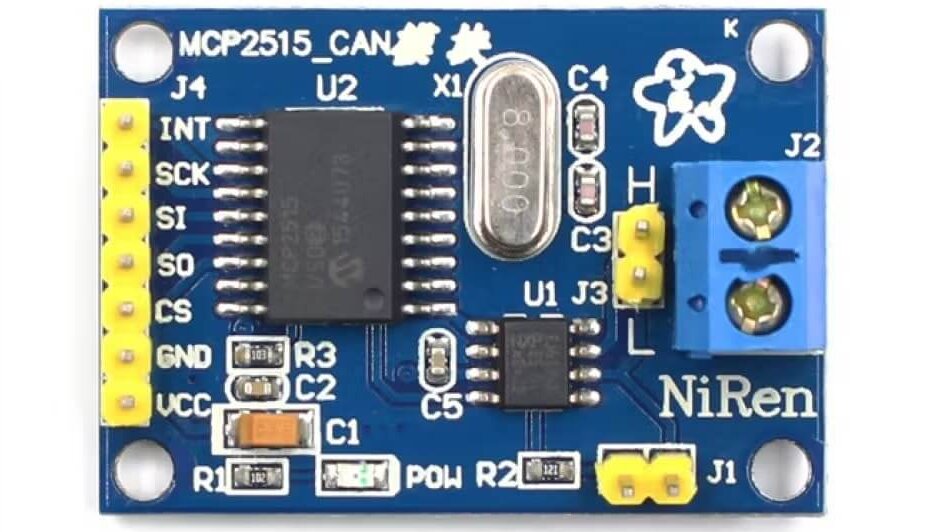
The MCP2515 CAN Bus Module is a compact and efficient communication module that supports CAN Protocol 2.0B at speeds up to 1 Mbps.
- MCP2515 Controller IC:
- TJA1050 Transceiver IC:
Specifications
- High-speed CAN transceiver (TJA1050)
- Module dimensions: 40×28mm
- Supports up to 112 nodes
- Low current standby mode
- LED indicators and independent buttons for diagnostics
Examples of CAN Applications
- Building automation
- Elevators
- Ships
- Lighting systems
- Agricultural machinery
- Industrial automation
- Medical devices
Vehicle Monitoring With MCP2515 CAN Bus & Arduino
Wiring and Connections
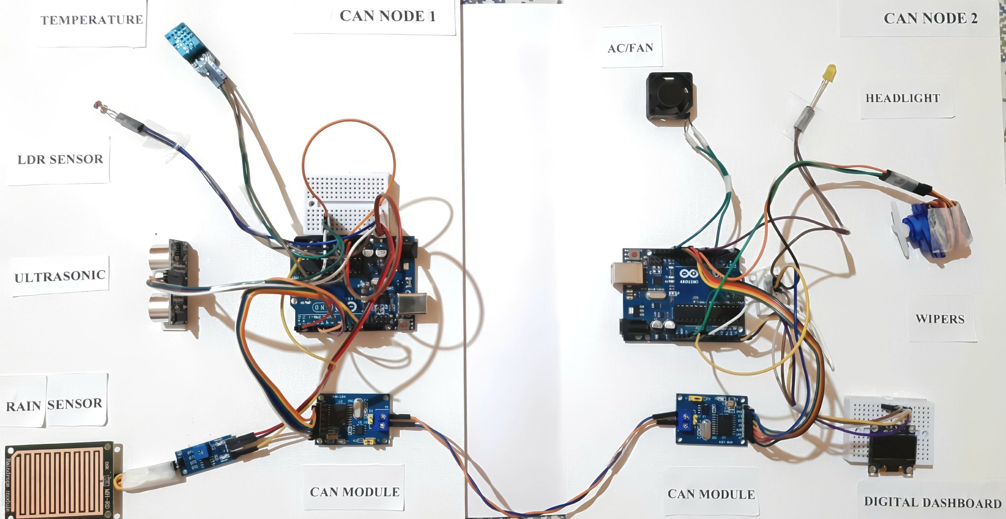
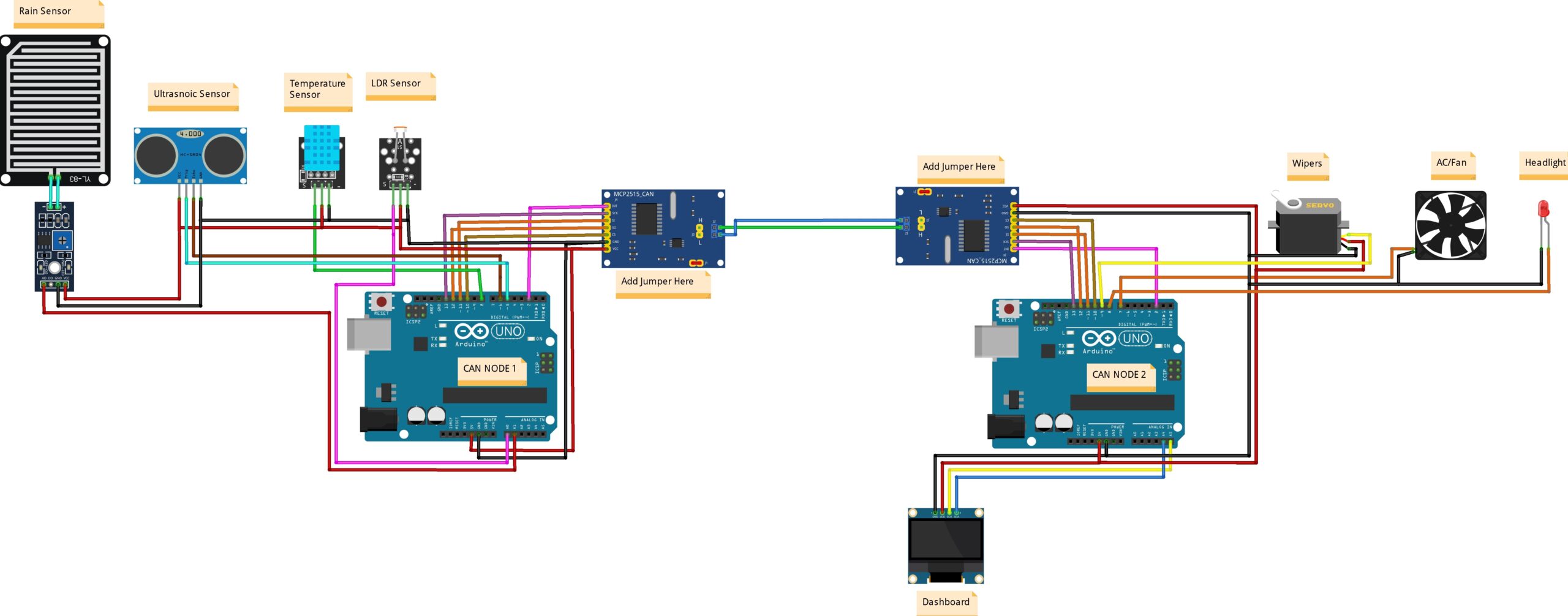
Node 1
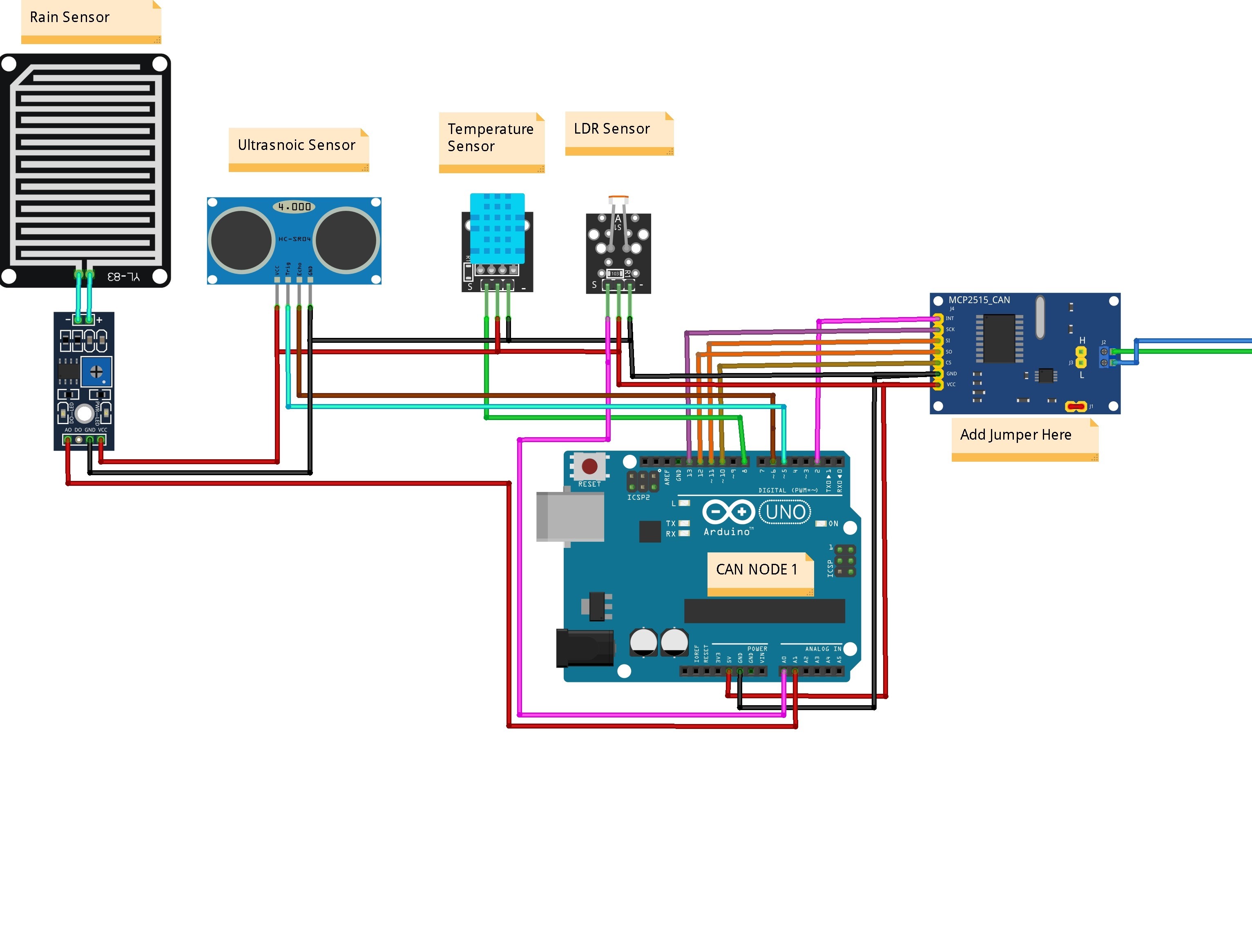
Node 1 is equipped with sensors to monitor environmental and vehicle conditions. The connections are as follows:
- Ultrasonic Sensor (HC-SR04):
- Trig Pin → D5
- Echo Pin → D6
- Temperature Sensor (DHT11): Signal Pin → D8
- LDR Sensor: Signal Pin → A0
- Rain Sensor: Connected to Arduino’s → A1
The MCP2515 CAN Module handles the transmission of sensor data:
- CS → D10, SO (MISO) → D12, SI (MOSI) → D11, SCK → D13
- VCC → 5V, GND → GND
Node 2 (Actuators and Display Dashboard)
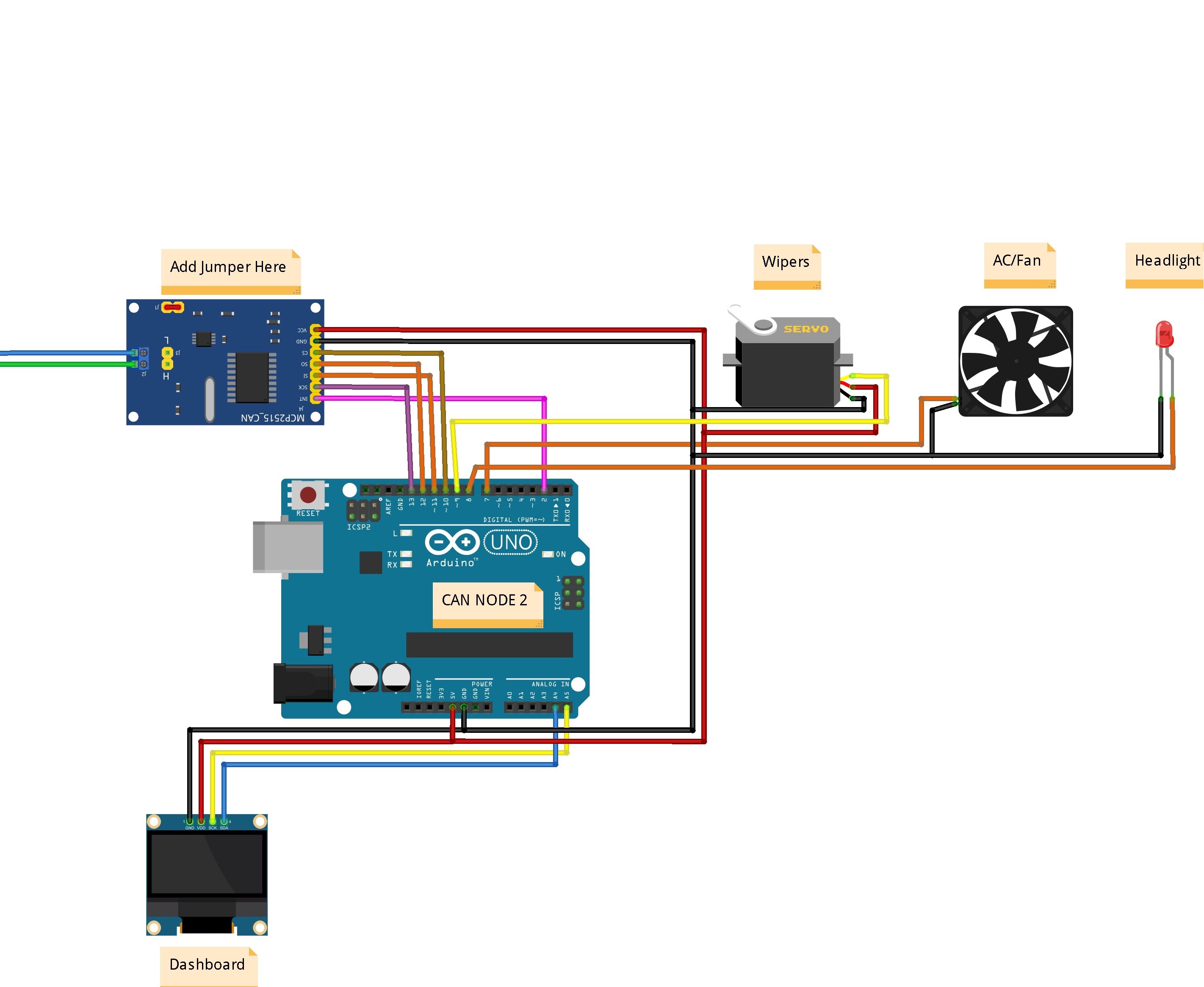
Node 2 receives data from Node 1 and operates actuators accordingly. The connections are:
- Servo Motor (Wipers): Signal Pin → D9
- Fan (AC): Signal Pin → D7
- LED (Headlight): Pin → D8
The OLED Display acts as the dashboard:
- SCL → A5, SDA → A4
- VCC → 5V, GND → GND
The MCP2515 CAN Module communicates with Node 1:
- CS → D10, SO (MISO) → D12, SI (MOSI) → D11, SCK → D13
- VCC → 5V, GND → GND
CAN Bus Wiring:
- CAN_H and CAN_L of MCP2515 modules on Node 1 and Node 2 are connected via two wires for communication.
Add a 120-ohm termination jumper to one MCP2515 module to ensure proper CAN communication.
Source Code/Program for Vehicle Monitoring With MCP2515 CAN Bus
Receiver Code
Before starting the coding part of the project, we need to install the MCP2515 CAN Bus Library on the Arduino IDE. Download the library from the following link and add it to the Arduino Library folder.
The code is divided into two parts: CAN transmitter code and CAN Receiver code.
Transmitter Code
|
1 2 3 4 5 6 7 8 9 10 11 12 13 14 15 16 17 18 19 20 21 22 23 24 25 26 27 28 29 30 31 32 33 34 35 36 37 38 39 40 41 42 43 44 45 46 47 48 49 50 51 52 53 54 55 56 57 58 59 60 61 62 63 64 65 66 67 68 69 70 71 72 |
#include <SPI.h> #include <DHT.h> const int SPI_CS_PIN = 10; const int CAN_INT_PIN = 2; #include "mcp2515_can.h" mcp2515_can CAN(SPI_CS_PIN); // Set CS pin //**************************** DEFINING PINS FOR PROJECT **************************// #define ldrPin A0 const int echoPin = 6; const int trigPin = 5; #define rainPin A1 #define DHTPIN 8 // Digital pin connected to the DHT sensor #define DHTTYPE DHT11 // DHT 11 DHT dht(DHTPIN, DHTTYPE); void setup() { SERIAL_PORT_MONITOR.begin(115200); dht.begin(); //**************************** CONFIGURE PIN_MODE FOR SENSORS *************************// pinMode(ldrPin, INPUT); pinMode(echoPin, INPUT); pinMode(trigPin, OUTPUT); pinMode(rainPin, INPUT); while (CAN_OK != CAN.begin(CAN_500KBPS)) { SERIAL_PORT_MONITOR.println("CAN init fail, retry..."); delay(100); } SERIAL_PORT_MONITOR.println("CAN init ok!"); } void loop() { unsigned char ldrStatus = analogRead(ldrPin); SERIAL_PORT_MONITOR.print("LDR STATUS "); SERIAL_PORT_MONITOR.println(ldrStatus); unsigned char rainStatus = analogRead(rainPin); SERIAL_PORT_MONITOR.print("RAIN STATUS "); SERIAL_PORT_MONITOR.println(rainStatus); int t = dht.readTemperature(); SERIAL_PORT_MONITOR.print("TEMP "); SERIAL_PORT_MONITOR.println(t); digitalWrite(trigPin, LOW); delayMicroseconds(2); digitalWrite(trigPin, HIGH); delayMicroseconds(10); digitalWrite(trigPin, LOW); float duration = pulseIn(echoPin, HIGH); int distance = (duration*.0343)/2; SERIAL_PORT_MONITOR.print("Safe Distance "); SERIAL_PORT_MONITOR.println(distance); uint8_t sensor_data[] = { ldrStatus,rainStatus,t,distance }; // send data: id = 0x70, standard frame, data len = 8, stmp: data buf CAN.sendMsgBuf(0x70, 0, 4, sensor_data); delay(2000); } |
Receiver
|
1 2 3 4 5 6 7 8 9 10 11 12 13 14 15 16 17 18 19 20 21 22 23 24 25 26 27 28 29 30 31 32 33 34 35 36 37 38 39 40 41 42 43 44 45 46 47 48 49 50 51 52 53 54 55 56 57 58 59 60 61 62 63 64 65 66 67 68 69 70 71 72 73 74 75 76 77 78 79 80 81 82 83 84 85 86 87 88 89 90 91 92 93 94 95 96 97 98 99 100 101 102 103 104 105 106 107 108 109 110 111 112 113 114 115 116 117 118 119 120 121 122 123 124 125 126 |
#include <Wire.h> #include <SPI.h> #include <Servo.h> #include <Adafruit_GFX.h> #include <Adafruit_SSD1306.h> #include "mcp2515_can.h" #define CAN_2515 Servo servo; const int SPI_CS_PIN = 10; const int CAN_INT_PIN = 2; mcp2515_can CAN(SPI_CS_PIN); #define SCREEN_WIDTH 128 // OLED display width, in pixels #define SCREEN_HEIGHT 64 // OLED display height, in pixels #define OLED_RESET -1 // Reset pin # (or -1 if sharing Arduino reset pin) Adafruit_SSD1306 display(SCREEN_WIDTH, SCREEN_HEIGHT, &Wire, OLED_RESET); const int ledPin = 8; const int ACPin = 7; void setup() { SERIAL_PORT_MONITOR.begin(115200); pinMode(ACPin, OUTPUT); pinMode(ledPin, OUTPUT); pinMode(4, OUTPUT); servo.attach(9); while (CAN_OK != CAN.begin(CAN_500KBPS)) { // init can bus : baudrate = 500k SERIAL_PORT_MONITOR.println("CAN init fail, retry..."); delay(100); } SERIAL_PORT_MONITOR.println("CAN init ok!"); display.begin(SSD1306_SWITCHCAPVCC, 0x3C); display.clearDisplay(); } void loop() { display.clearDisplay(); display.setTextSize(1); display.setTextColor(SSD1306_WHITE); digitalWrite(4, HIGH); unsigned char len = 0; unsigned char rxBuf[8]; if (CAN_MSGAVAIL == CAN.checkReceive()) { // check if data coming CAN.readMsgBuf(&len, rxBuf); // read data, len: data length, buf: data buf unsigned long canId = CAN.getCanId(); SERIAL_PORT_MONITOR.print("get data from ID: 0x"); SERIAL_PORT_MONITOR.println(canId, HEX); SERIAL_PORT_MONITOR.println(rxBuf[0]); SERIAL_PORT_MONITOR.println(rxBuf[1]); SERIAL_PORT_MONITOR.println(rxBuf[2]); SERIAL_PORT_MONITOR.println(rxBuf[3]); display.setCursor(8, 0); display.print("Range Rover DASHBOARD"); if(rxBuf[0] > 5){ digitalWrite(ledPin, HIGH); display.setCursor(0, 50); display.print(" HEADLIGHTS: ON"); } else{ digitalWrite(ledPin, LOW); display.setCursor(0, 50); display.print(" HEADLIGHTS: OFF"); } display.setCursor(0, 36); display.print(" WIPERS : "); if(rxBuf[1] < 165){ display.setCursor(82, 36); display.print("ON"); servo.write(180); delay(500); servo.write(0); delay(500); } else{ display.setCursor(82, 36); display.print("OFF"); } float temperature = rxBuf[2]; if(temperature >= 30){ digitalWrite(ACPin, HIGH); delay(1000); } else{ digitalWrite(ACPin, LOW); } display.setCursor(0, 24); display.print(" TEMP : "); display.setCursor(82, 24); display.print(temperature); float distance = rxBuf[3]; display.setCursor(0, 12); display.print(" SAFE DIST : "); display.setCursor(82, 12); display.print(distance); display.display(); } } |
Project Testing & Working
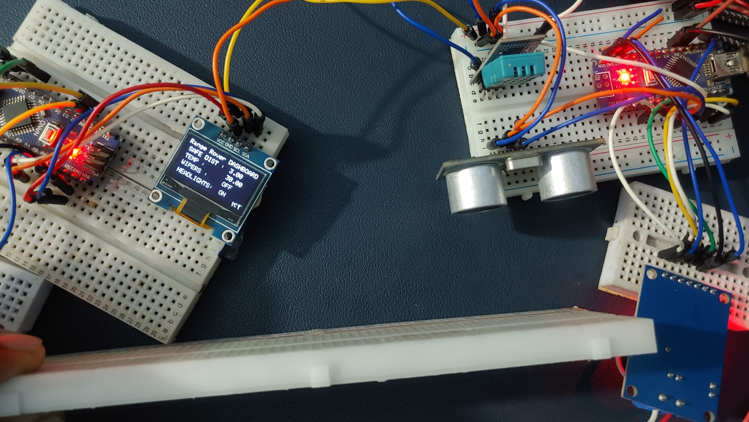
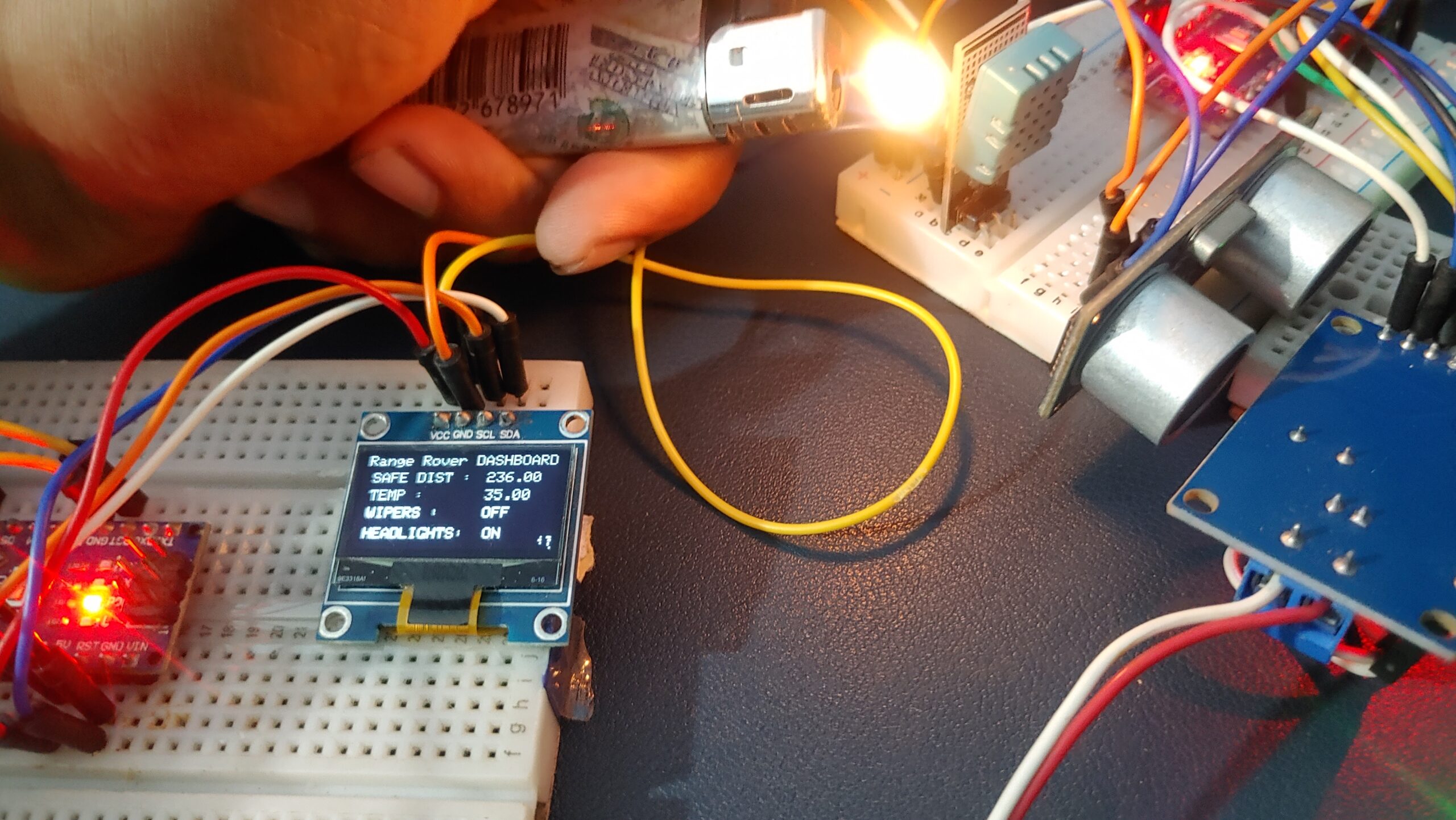
The system integrates sensors, CAN communication protocols, and actuators to respond to environmental conditions.
- Actuator Activation:
The microcontroller interprets the sensor data at the receiving end and activates specific actuators as required. Here’s how each actuator functions:

