Introduction
In this guide, we’ll show you how to Control WS2812 LED With Raspberry Pi Pico W & Adafruit IO platform. You’ll learn how to connect the pixels to the Pico, and how to control them with the Adafruit IO dashboard. You’ll also learn how to set up an Adafruit IO dashboard to control your NeoPixels in real-time.
This tutorial covers how to get data from Adafruit IO. Use the data from Adafruit IO to control NeoPixel RGB LED. Use MicroPython code to control the Raspberry Pi Pico. Raspberry Pi Pico W Getting Started Tutorial
Thank You, PCBWay:
This project is successfully completed because of the support and help from PCBWay. Guys if you have a PCB project, please see their website and get exciting bargains and coupons.
PCBway is the best prototype PCB company offering great PCB boards at lower prices If you sign-up using this link you will get beginner and sign-up coupon rewards. https://www.pcbway.com
Required Material
Diagram & Hardware Setup – WS2812 LED With Raspberry Pi Pico W
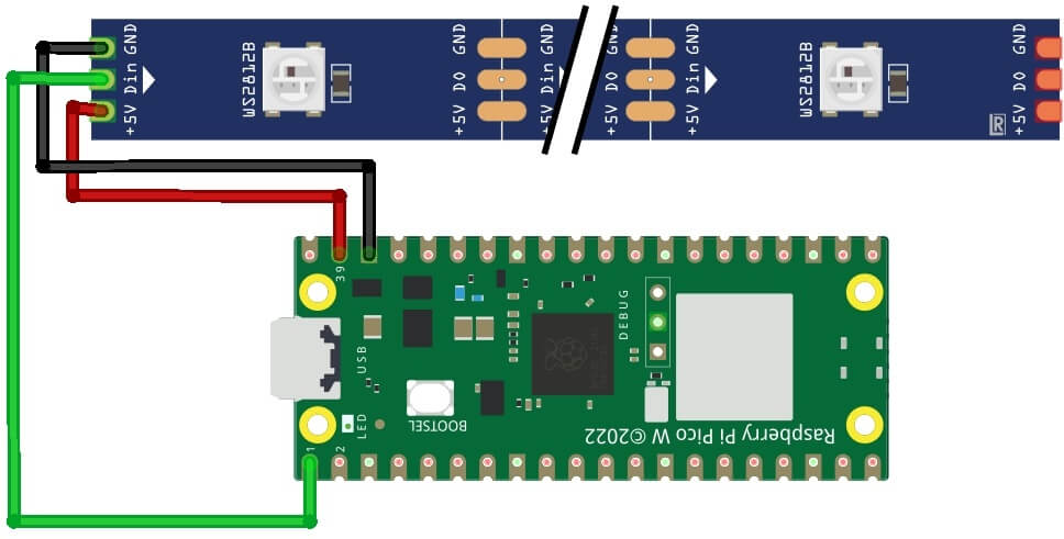
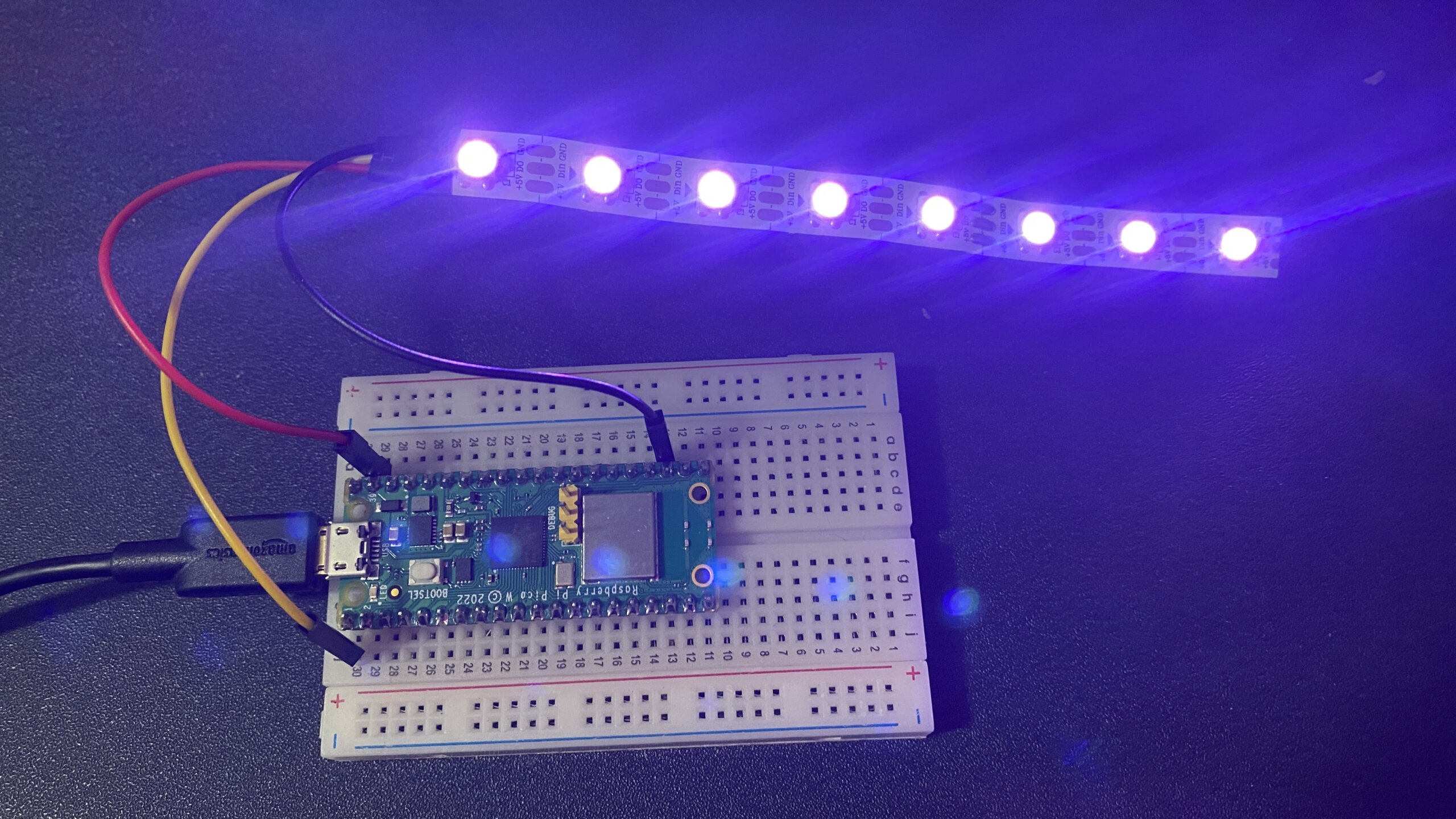
Let us set up the hardware for controlling the Addressable RGB LED Strip with Raspberry Pi Pico W & Adafruit IO. The wiring is very simple. The NeoPixel LED is also referred to as Addressable RGB LED because it allows users to independently control each LED. And, after assembling it will be controlled by the Adafruit.io platform
- DIN from NeoPixel strip to GP8 on Raspberry PI Pico W
- 5V from NeoPixel strip to VSYS on Raspberry PI Pico W
- GND from NeoPixel strip to GND on Raspberry PI Pico W
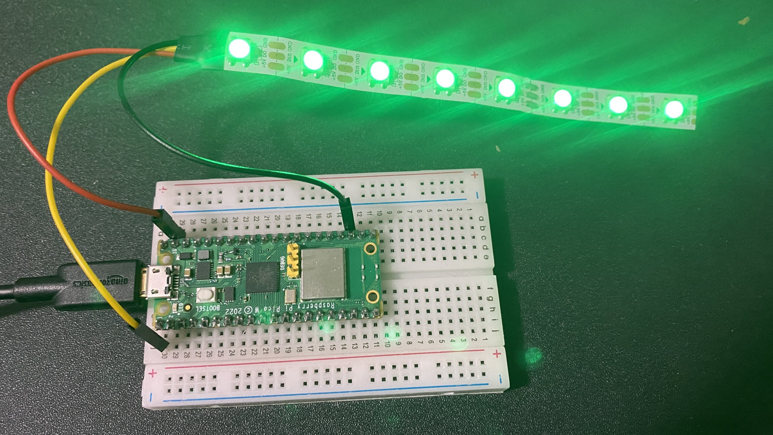
Attach the 5V, GND, and output wires of the RGB LED strip to the VSYS, GND and GP6 pins of the Raspberry PI Pico W, respectively. It is recommended to use at least 8 individual LEDs; this guide utilises 8 for this project.
To power 10 NeoPixels or more, you should use an external power source to avoid taxing the microcontroller’s limited ability to provide current.
Setup Adafruit IO Feeds & Dashboard
Set up an Adafruit IO Feeds & Dashboard to allow you to easily access your Adafruit IO data. Adafruit is an online retailer for makers and DIYers who love making something with electronics and programming. They offer a wide range of electronics and tools for makers of all skill levels.
Adafruit IO Setup
To begin working on the project, you need to create an account with Adafruit. Visit io.adafruit.com and follow the instructions to create a free account.
The way the code works is very simple. As you will see on the next heading, when you set up your dashboard, you will create 3 feeds and start changing the values using sliders. To do that click on the Feeds tab.
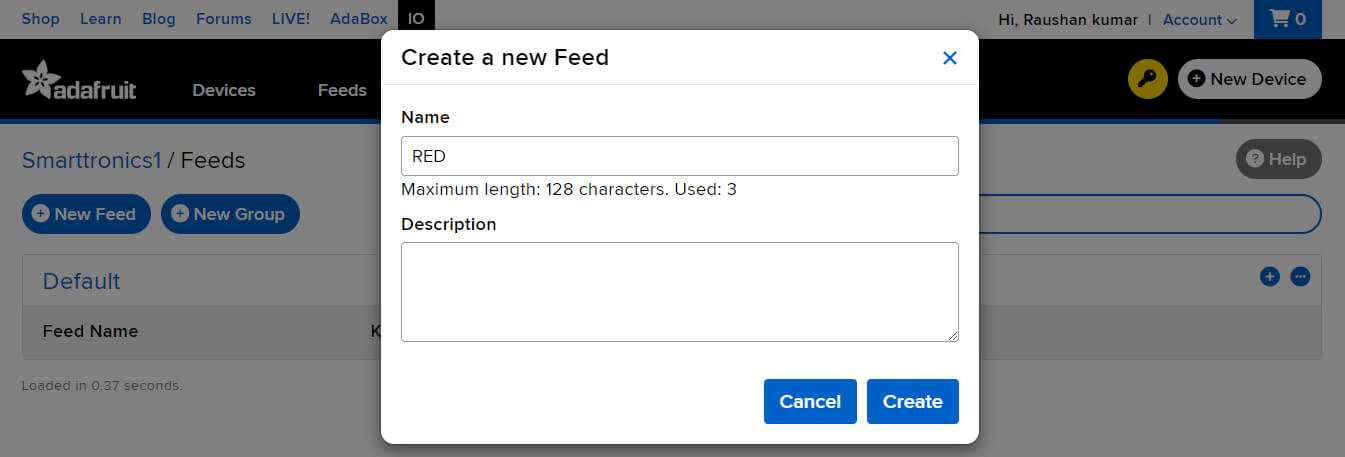
Click on “+New Feed” & give the feed name in RED and click on create.
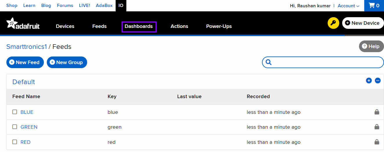
Repeat the method in the step above to create three feeds for Neopixels. Create 3 different feeds with names like RED, GREEN, & BLUE
Before proceeding, make sure your Neopixel group looks exactly like the screenshot below.
Adafruit IO Dashboard
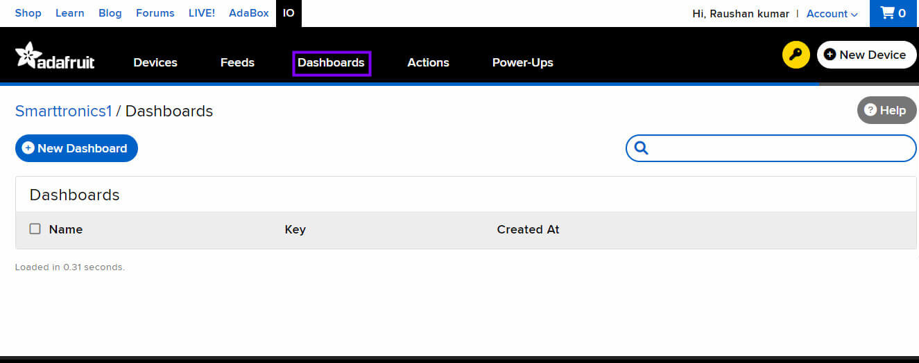
A dashboard lets you control devices, view reports and configure alerts. we need to visit the dashboard page, and this is done by clicking “Dashboard” in the left navigation menu.
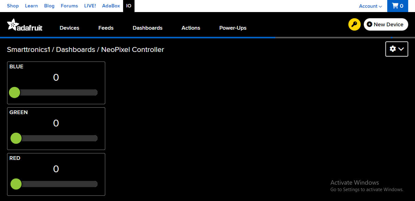
Give the name to the Dashboard as “NeoPixel Controller” and click on Create.
Click on the “NeoPixel Controller” to open the Dashboard
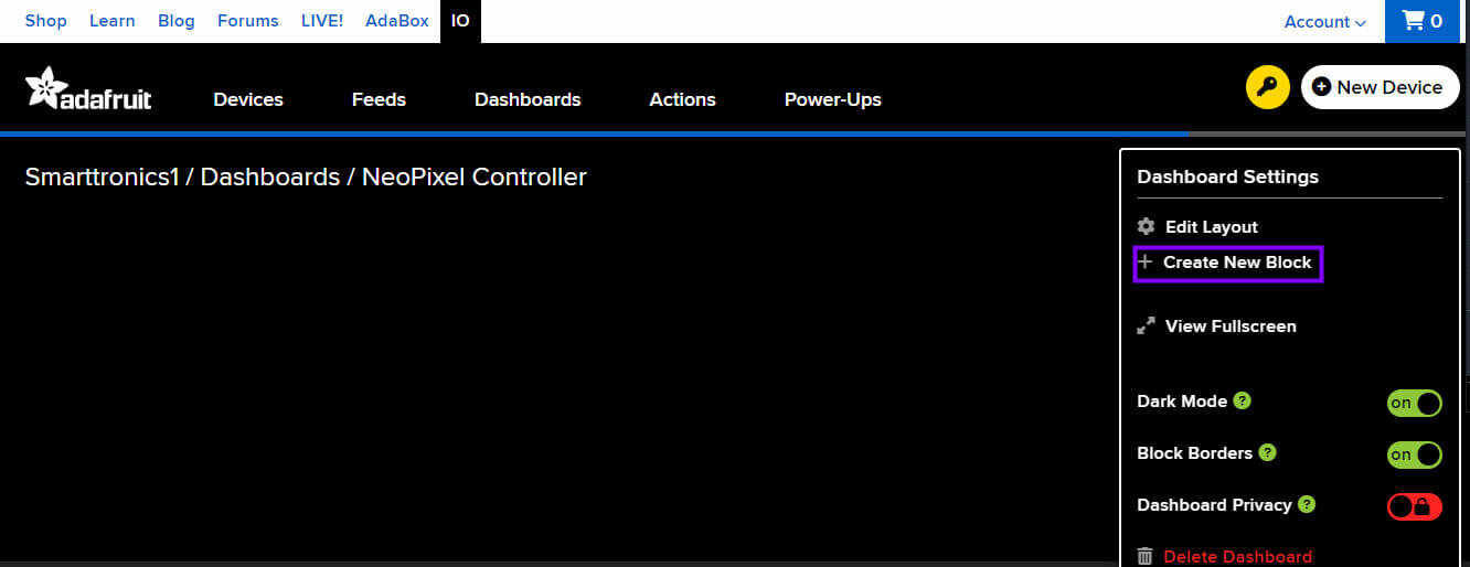
Click on the Setting icon of the dashboard. Here you will see multiple options like edit layout, create new layout along with Mode, and Block Borders setup.
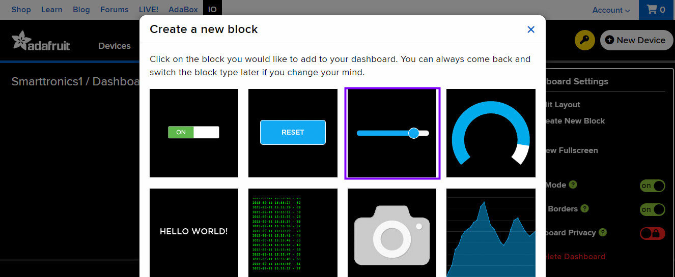
Click the ‘+’ button on your dashboard setting to add a new block.
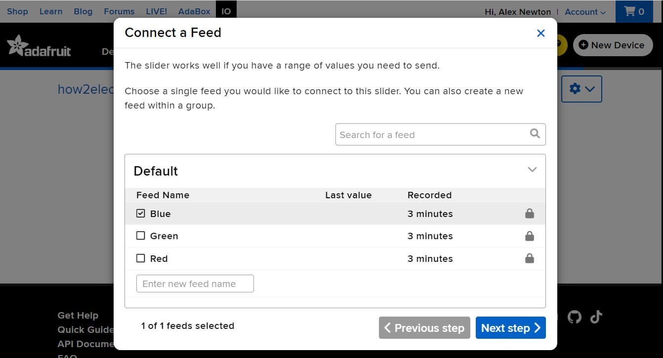
On the Choose Feed picker, select the Slider feed
Under Block Settings:
Setting the slider minimum and maximum values to 0 and 255 respectively and the slider step size to 1 creates a block.
Again, create the two remaining blocks in the same way and with the exact settings. There you go: your slider dashboard for R, G & B is ready.
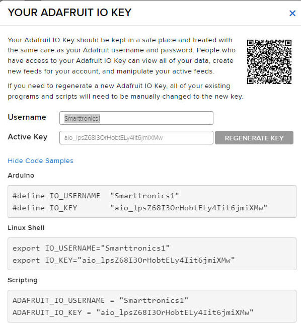
Now you can use the data with the sliders. The values of the three feeds are updated accordingly. Click on the Key symbol on the top right of the dashboard and from here you can copy the ‘username’ and ‘Adafruit IO Key’.
Finally, the software setup is complete. We need to move on to the programming part.
MicroPython Script
Now let us see the MicroPython Code to Control WS2812 NeoPixel RGB LED Strip with Raspberry Pi Pico W & Adafruit IO. It is easy to use REST APIs with Raspberry Pi Pico W and MicroPython to get data from Adafruit IO. – IoT server. It is very easy to use REST APIs with Raspberry Pi Pico W and MicroPython to get data from the Adafruit IO remote storage.
Thonny IDE Open a new Window and paste the following into it. You need to make some changes to the following lines of the code before running it.
|
1 2 3 4 |
wlan.connect("SSID","Password") aio_key = "Adafruit IO Key" username = "Adafruit IO Username" |
Replace the WiFi SSID and Password with your WiFi SSID Name and Password in the .ino file. Similarly, change the Adafruit IO Key and also the username
main.py
|
1 2 3 4 5 6 7 8 9 10 11 12 13 14 15 16 17 18 19 20 21 22 23 24 25 26 27 28 29 30 31 32 33 34 35 36 37 38 39 40 41 42 43 44 45 46 47 48 49 50 51 52 53 54 55 56 57 58 |
from machine import Pin from neopixel import NeoPixel from time import sleep import network import urequests as requests import ujson wlan = network.WLAN(network.STA_IF) wlan.active(True) wlan.connect("SSID","Password") # Adafruit IO authentication aio_key = "Adafruit IO Key" username = "Adafruit IO Username" headers = {'X-AIO-Key': aio_key, 'Content-Type': 'application/json'} # Don't forget the NeoPixels! np = NeoPixel(Pin(0), 8) feed_names = ['red', 'green', 'blue'] rgb_values = {'red': 0, 'green': 0, 'blue': 0} # connect the network wait = 10 while wait > 0: if wlan.status() < 0 or wlan.status() >= 3: break wait -= 1 print('waiting for connection...') time.sleep(1) # Handle connection error if wlan.status() != 3: raise RuntimeError('wifi connection failed') else: print('connected') ip=wlan.ifconfig()[0] print('IP: ', ip) def create_URL(feedname): url = "https://io.adafruit.com/api/v2/" + username + "/feeds/" + feedname + "/data/last" return url try: while True: for color in feed_names: response = requests.get(create_URL(color), headers=headers) parsed = ujson.loads(response.text) value = int(parsed['value']) rgb_values[color] = value print(value) for i in range(8): np[i] = (rgb_values['red'], rgb_values['green'], rgb_values['blue']) np.write() except KeyboardInterrupt: for i in range(8): np[i] = (0, 0, 0) np.write() time.sleep(0.5) |
Save the file to Raspberry Pi Pico W and name it Main.py. You can now run the code.
Controlling Neopixels LED with Raspberry Pi Pico W & Adafruit IO
After running the code, the Raspberry Pi Pico will connect to the WiFi Network using the WiFi SSID & Password. Then it establishes the connection with Adafruit IO using the API Key.
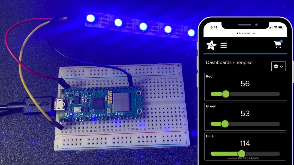
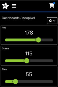
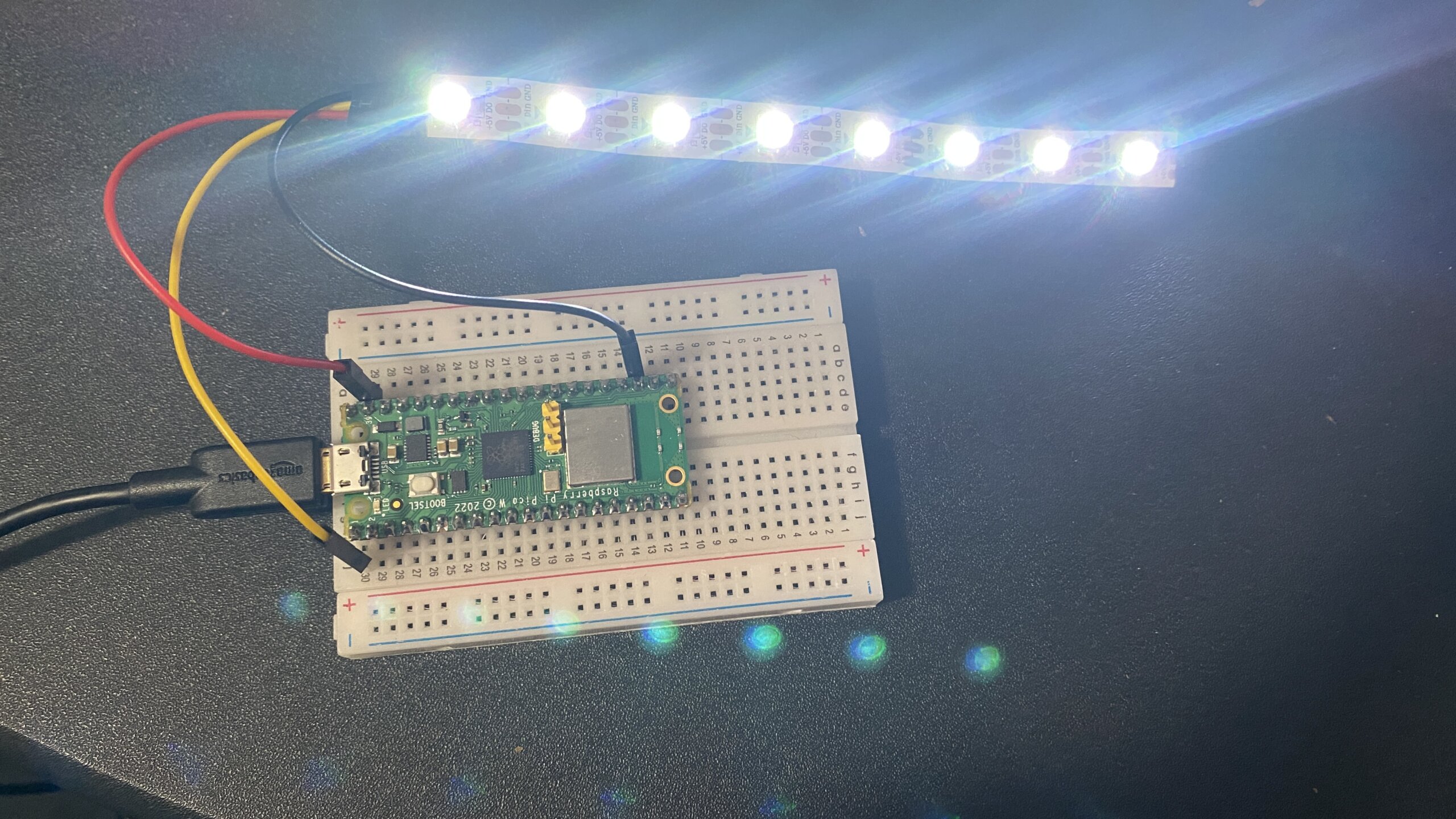
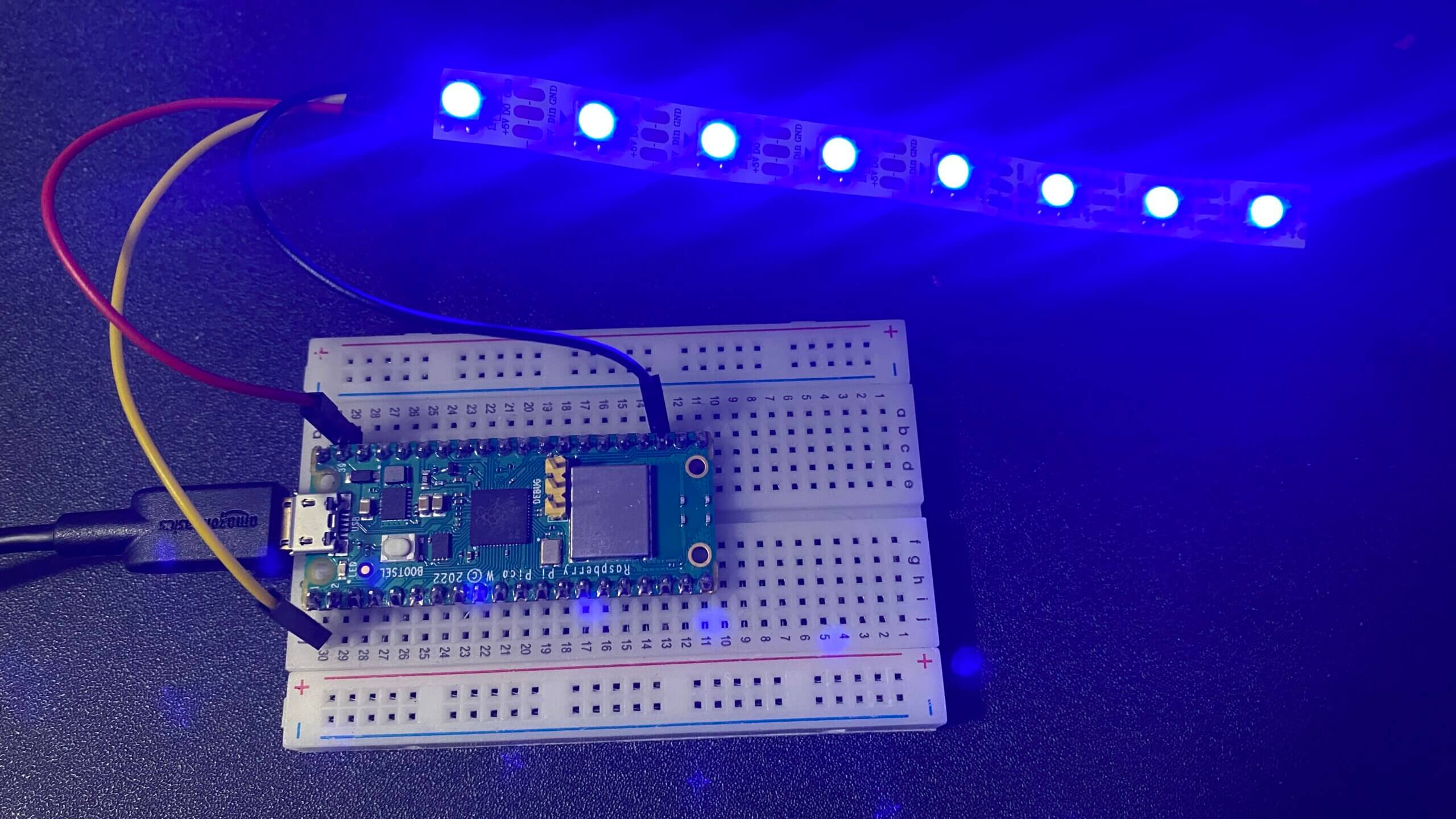
Now you can send commands from Adafruit IO Dashboard by sliding different slides. This will control the colour intensity and brightness.
The Pico W will start to monitor these values and change the LED RGB levels based on their values. the colour range for all red, green, and blue is 0 to 255. You can slide all three slides to control the RGB Color.
Conclusion
This tutorial shows how to control WS2812 LED with Raspberry Pi Pico W microcontroller and Adafruit IO. You can now WS2812 LED With Raspberry Pi Pico W microcontroller and Adafruit IO.
Here are some Raspberry Pi Pico Projects
- BME280 With Raspberry Pi Pico W Using MicroPython
- DS18B20 Temperature Sensor With Raspberry Pi Pico
- Interfacing HC-05 Bluetooth Module With Raspberry Pi Pico
- RFID Door Lock With Raspberry Pi Pico Using Micropython
-
Controlling RGB LED From Raspberry Pi Pico W Web Server with MicroPython





3 Comments
Pingback: Control NeoPixel LEDs with Raspberry Pi Pico W & Adafruit IO #PiDay #AdafruitIO @diyprojectslab @Raspberry_Pi « Adafruit Industries – Makers, hackers, artists, designers and engineers!
Pingback: Management NeoPixel LEDs with Raspberry Pi Pico W & Adafruit IO #PiDay #AdafruitIO @diyprojectslab @Raspberry_Pi « Adafruit Industries – Makers, hackers, artists, designers and engineers! – PiGurus
Pingback: How to Control WS2812 LED w/ Raspberry Pi Pico W & Adafruit IO – Titre du site