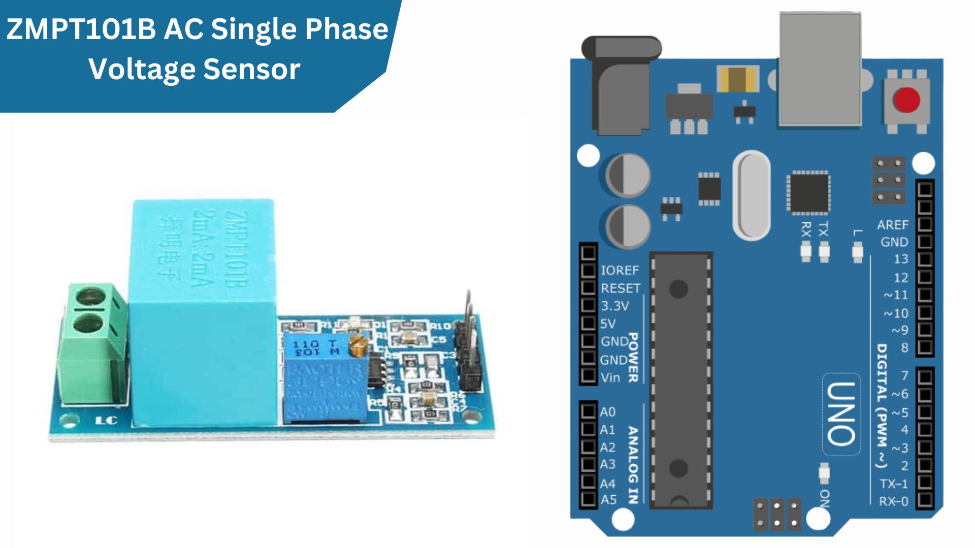
In this tutorial, we will be hooking up a ZMPT101B Voltage Sensor Module with Arduino. This module can be used for AC or DC voltage measurements and provides both analog and digital outputs. We will be using the analog output in this tutorial. the module has a range of 0-250V and an accuracy of 1%.
We’ll go over how to wire the sensor, how to set up the Arduino sketch, and how to read the sensor data. It can be used to measure the voltage in your home or office. checkout my previous post on Measure AC Current Using Arduino And SCT-013 Sensor
Required Components
- ZMPT101B Voltage Sensor Module
- Arduino board
- Jumper wires
- Breadboard
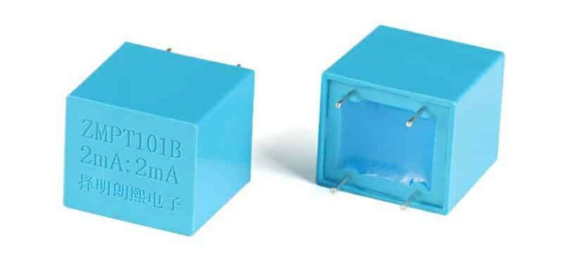
ZMPT101B Voltage Transformer
ZMPT 101B is a high-precision voltage transformer that makes it easy to monitor AC mains voltage up to 1000 volts.
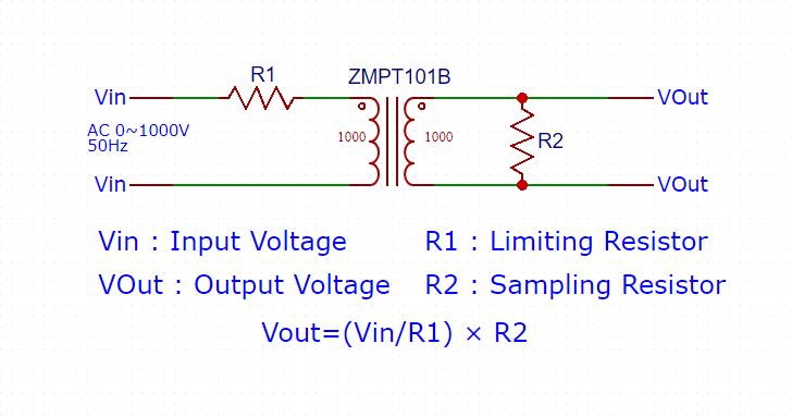
This transformer holds up to 4kV per breakdown voltage, the ratio of turns is 1: 1, but this is a current transformer of 2mA: 2mA. We feed it a current and remove the current. The input current is simply set by the resistor in series R1, and we use a sampling resistor R2 in parallel to get the output voltage.
Schematic ZMPT101B Voltage Transformer
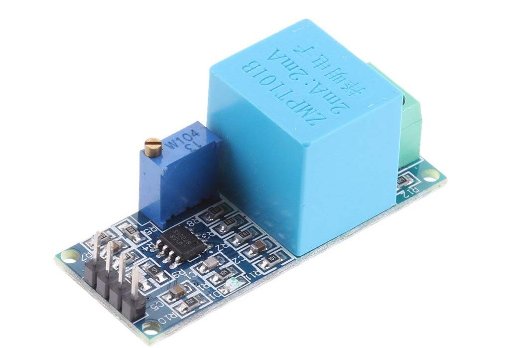
ZMPT101B Voltage Sensor Module
The ZMPT101B Voltage Sensor Module is a small electronic device that allows you to measure AC voltage using an Arduino or other microcontroller. It converts the AC voltage into a signal that the microcontroller can understand. With this module, you can easily measure AC voltage in your projects, It is commonly used in applications such as power monitoring, home automation, smart energy meter management, and system analysis.
ZMPT101B is the best choice to measure the AC voltage using Arduino/ESP8266/Raspberry Pi. In many electrical projects, the engineer directly deals with measurements with few basic requirements like
- High galvanic isolation
- Wide Range
- High accuracy
- Good Consistency
Circuit Diagram & Schematic
The ZMPT101B module is built with an LM358N IC chip, a some resistors, and few capacitor that helps reduce noise, or unwanted electrical signals.
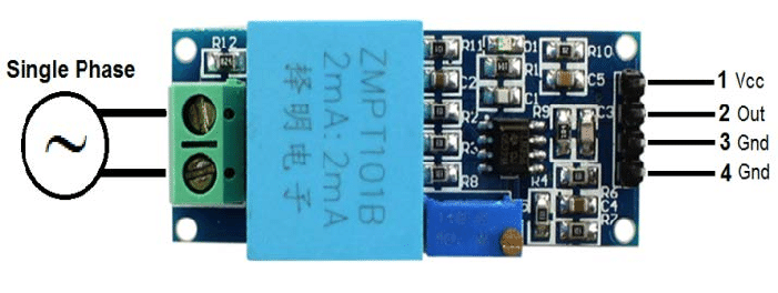
Pinout of ZMPT101B Module
The ZMPT101B module has 4 pins:
- VCC
- OUT
- GND
- GND
Specifications of ZMPT101B Module
- Operating Voltage: 5V
- Maximum Input Voltage: 250V (AC)
- Turn Ratio: 1:1
- Input Current Range: 2mA – 10mA
- Operating temperature : 40ºC ~ + 70ºC
- Output Voltage: Varies based on input voltage and current
- Breakdown Voltage: Up to 4kV
- Accuracy: High precision for voltage measurements
- Compatible with Arduino
Applications
- Electrical energy meters
- AC Voltage measurement
- Household electrical equipment
- Industrial apparatuses
- Electrical testing equipment
Interfacing ZMPT101B Voltage Sensor Module with Arduino
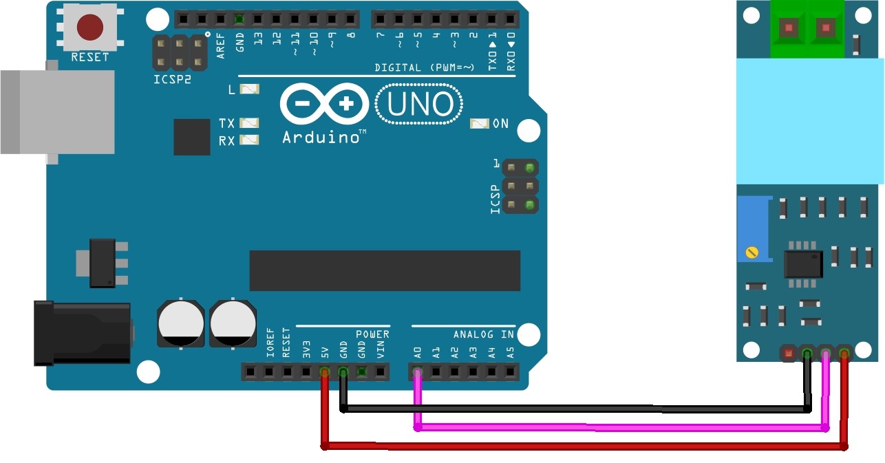
Here is a connection diagram that can be used to interface the sensor with the Arduino
Connect the VCC, GND,& OUT pin of ZMPT101B to 5V, GND, & A0 of Arduino respectively.
AC Voltage Sensor Sample Program
|
1 2 3 4 5 6 7 8 9 |
void setup() { Serial.begin(9600); } void loop() { Serial.println(analogRead(A0)); delay(100); } |
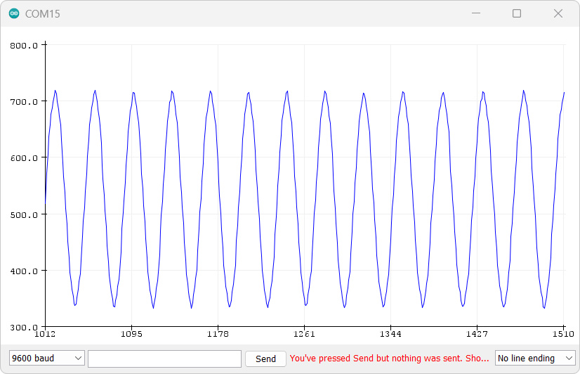
After uploading the code to your Arduino board, open the Serial Plotter from the Tools menu in the Arduino IDE. When nothing is connected to the module inputs, you should see a value of around 512 (2.5 volts) on the Serial Plotter. If you apply 220V AC to the input, you should see a sinusoidal voltage diagram on the Serial Plotter.
The Single Phase AC Voltage Module provides an analog output ranging from 0 to 1023, representing the measured voltage.
Turn the potentiometer on the module to get the most perfect sine wave possible, as in the following picture.
Note: Make sure the sine wave on the serial plotter is fully visible, including the highest and lowest points. Adjust the potentiometer on the module if any part of the waveform is missing. This is important to avoid measurement errors in the next step.
Source Code
Here is a sample code for interfacing the ZMPT101B Voltage Sensor module with Arduino.
Ac_Volt_Cal
|
1 2 3 4 5 6 7 8 9 10 11 12 13 14 15 16 17 18 19 20 21 22 23 24 25 26 27 28 29 30 31 32 |
int adc_max = 0; // Variable to store the maximum sensor value int adc_min = 1023; // Variable to store the minimum sensor value long tiempo_init; // Variable to store the initial time void setup() { Serial.begin(115200); // Initialize the serial communication tiempo_init = millis(); // Get the current time in milliseconds } void loop() { if ((millis() - tiempo_init) > 500) { // Check if 500 milliseconds have passed adc_max = 0; // Reset the maximum sensor value adc_min = 1023; // Reset the minimum sensor value tiempo_init = millis(); // Update the initial time } int sensorValue = analogRead(A0); // Read the analog input from pin A0 if (sensorValue > adc_max) { adc_max = sensorValue; // Update the maximum value if a new maximum is found } else if (sensorValue < adc_min) { adc_min = sensorValue; // Update the minimum value if a new minimum is found } // Print the maximum and minimum values to the serial monitor Serial.print("adc_max: "); Serial.print(adc_max); Serial.print(" adc_min: "); Serial.println(adc_min); delay(1); // Small delay for stability between each iteration } |
Upload the program: Ac_Volt_Cal
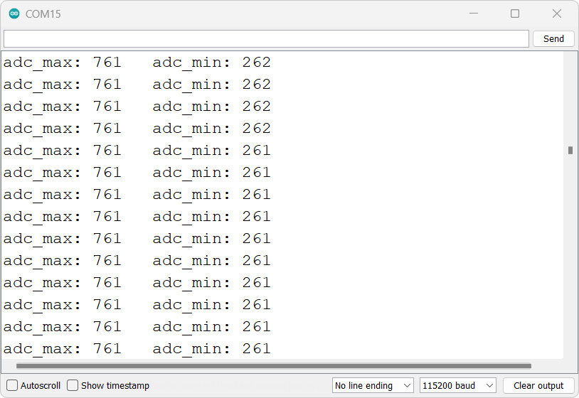
- This program is used to obtain calibration values for the sensor.
- Adjust the potentiometer to set the values of
adc_maxandadc_min. - It is recommended to turn the potentiometer counterclockwise until
adc_maxreaches 700+. - Take note of the values
adc_maxandadc_min. - Use a multimeter to measure the AC voltage and record it.
Ac_Volt_inst
|
1 2 3 4 5 6 7 8 9 10 11 12 13 14 15 16 17 18 19 20 21 22 23 24 25 26 27 28 29 30 31 32 33 34 35 36 37 38 39 40 41 42 43 44 45 46 47 48 |
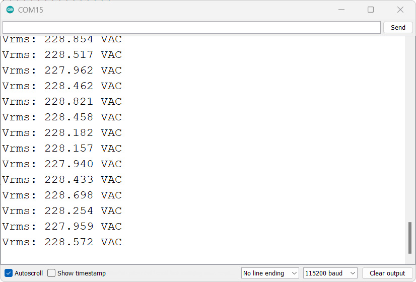
// Calibration values obtained from the sketch: volt_ac_cal int adc_max = 760; // Maximum sensor value during calibration int adc_min = 261; // Minimum sensor value during calibration float volt_multi = 231; // RMS voltage obtained from a multimeter float volt_multi_p; // Peak voltage float volt_multi_n; // Negative peak voltage void setup() { Serial.begin(115200); volt_multi_p = volt_multi * 1.4142; // Peak voltage = RMS voltage * 1.4142 (Single-phase current) volt_multi_n = -volt_multi_p; // Negative peak voltage } void loop() { float volt_rms = get_voltage(); // Root Mean Square voltage (V-RMS) Serial.print("Vrms: "); Serial.print(volt_rms, 3); Serial.println(" VAC"); // Delay for a certain interval if needed //delay(100); } float get_voltage() { float adc_sample; float volt_inst = 0; float sum = 0; float volt; long init_time = millis(); int N = 0; while ((millis() - init_time) < 500) { // Duration of 0.5 seconds (Approximately 30 cycles of 60Hz) adc_sample = analogRead(A0); // Sensor voltage volt_inst = map(adc_sample, adc_min, adc_max, volt_multi_n, volt_multi_p); sum += sq(volt_inst); // Sum of Squares N++; delay(1); } //Serial.print("N: "); //Serial.println(N); volt = sqrt(sum / N); // RMS equation return volt; } |
Load the program: Ac_Volt_inst
- This program is the final working program.
- It requires three values:
adc_max,adc_min, and the AC voltage is measured by the multimeter. - Set the values of
adc_maxandadc_minobtained from the calibration. - Adjust the
volt_multivariable to match the measured AC voltage (default is 222VAC).
Please note that this is just a basic overview. I will continue working on ZMPT101B and share my thoughts once I make more progress. I’m also interested to see if anyone else has made any new discoveries with this sensor module. Remember, expertise is for everyone!

