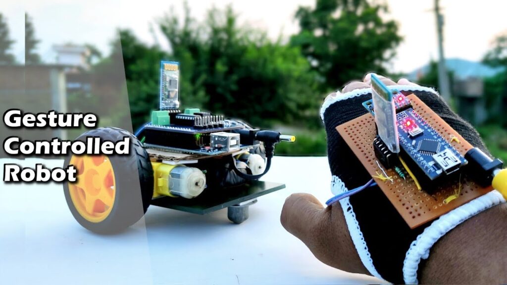
Hey Friends Today we will learn How To make Arduino Gesture Control Car using Arduino. This Gesture Control Robot is based on Arduino Nano, MPU6050, Hc-05 Bluetooth Module Pair and Motor Driver shield. Control Car Like a Super Hero. Basically this is a simple application of MPU-6050 3-axis Gyroscope, Accelerometer You can make a lot Projects if you understand and How to Interface it with microcontroller and how to transfer its data over the Bluetooth modules. It is very easy to make if you understand. it’s a cool project and very simple!
This project is essentially made of two-part, the Transmitter placed on the hand and the Receiver one which is the car chassis.
The different gestures that have been mapped to the direction of the Robot Car are-
- Hand parallel to the ground-stationary
- Hand tilted forward-forward
- Hand tilted backward-backward
- Hand tilted right-right
- Hand tilted left-left
I’ve made the transmitter made on a glove.
What Is a Robot ?
Robot is an electromechanical device which is capable of reacting in some way to its environment, and take autonomous decisions or actions in order to achieve a specific task.
A robot is consists of following components
- Structure / Chassis
- Actuator / Motor
- Controller
- Inputs / Sensors
- Power Supply
In the next steps I will describe each of the above components, so that you can understand easily.
Required Material – Arduino Gesture Control Car
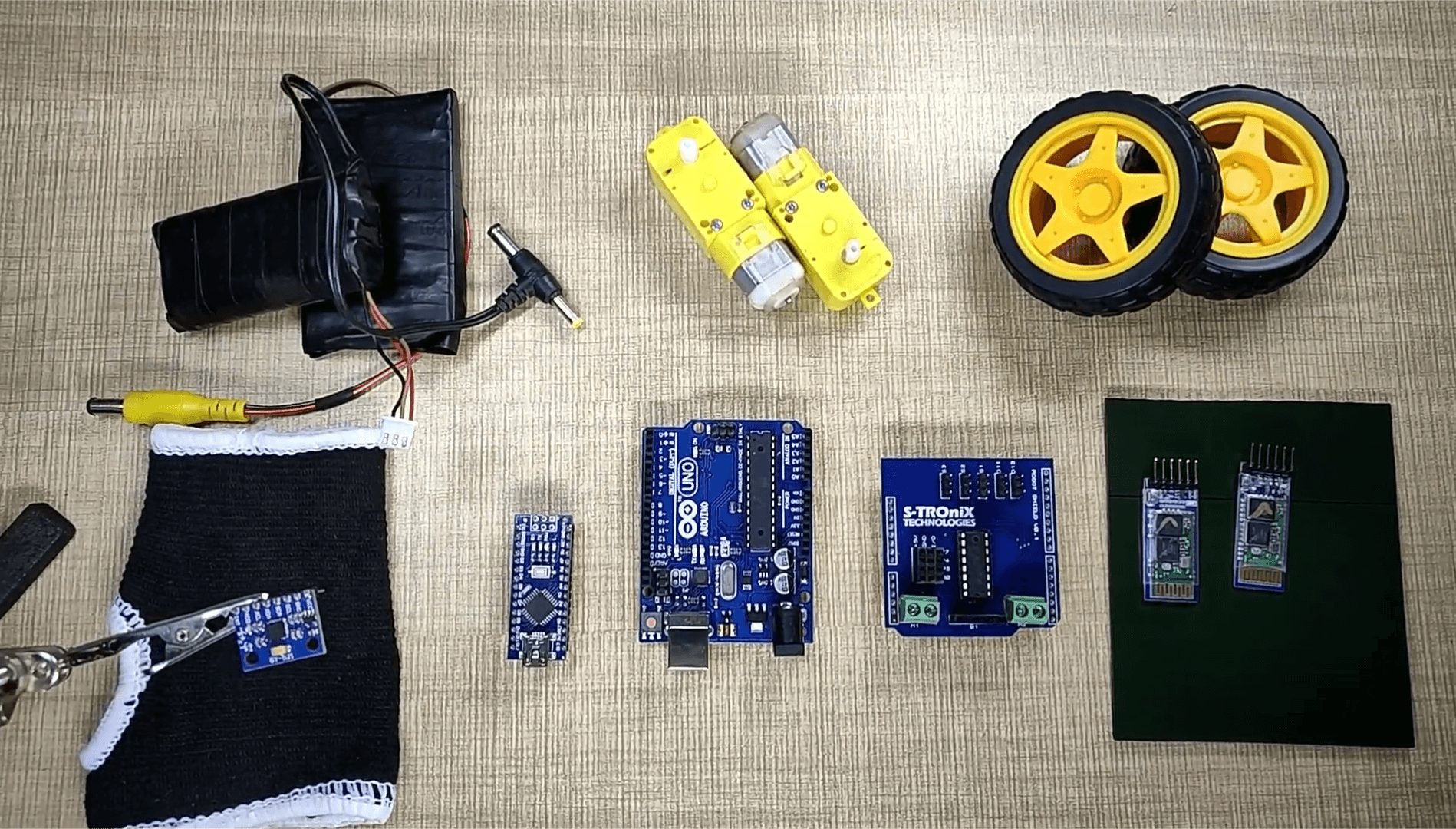
You’ll need Some components for making this
- 1× Arduino nano
- 1× Arduino UNO
- 2× BO Motor
- 2× wheel
- 1× l293D IC
- 1× 7.4Volt lipo battery
- 1× zero PCB
- 2× connectors
- 2× bluetooth module
- 1× MPU6050
- 1pcs Gloves
MPU6050
The MPU6050 is one of the most commonly used Sensor Modules by hobbyists and enthusiasts. It consist Three-axis accelerometer and three-axis gyroscope and a Digital motion processor integrated on a single chip. it used to measure the position and the acceleration of the device.
Circuit Diagram for Arduino Gesture Control Car
This Arduino Gesture Controller Car Using Blutooth. hardware is divided into two sections
- Transmitter
- Receiver
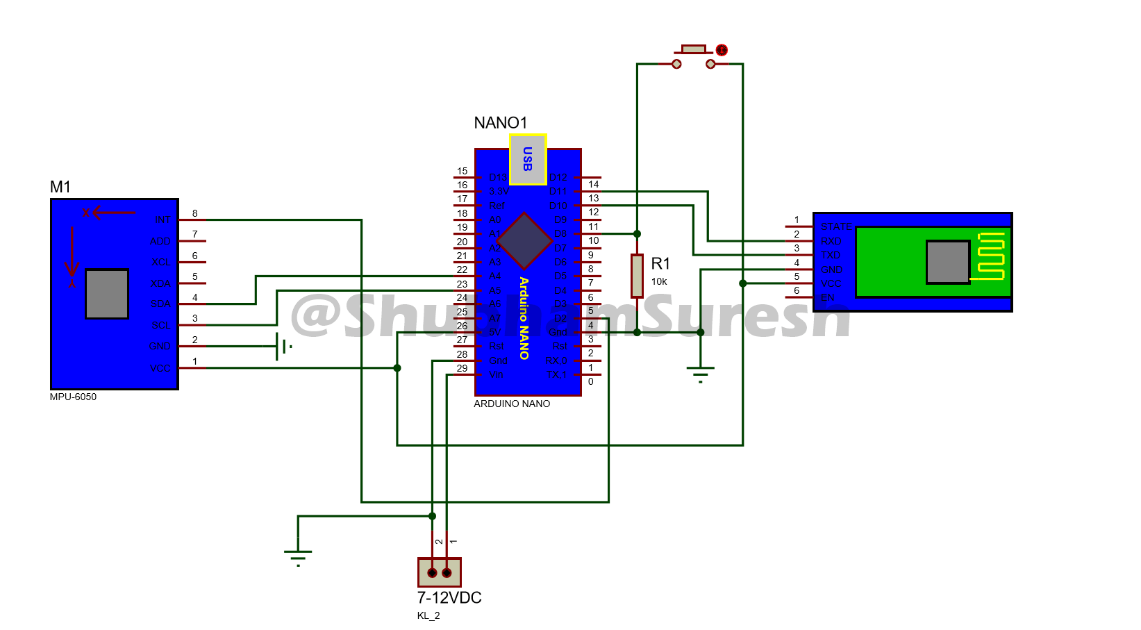
Transmitter Circuit for Arduino Gesture Control Car
Contains
- Arduino nano
- MPU6050Ssensor
- HC-05Bluetooth module
- Push-button
- battery 9v.
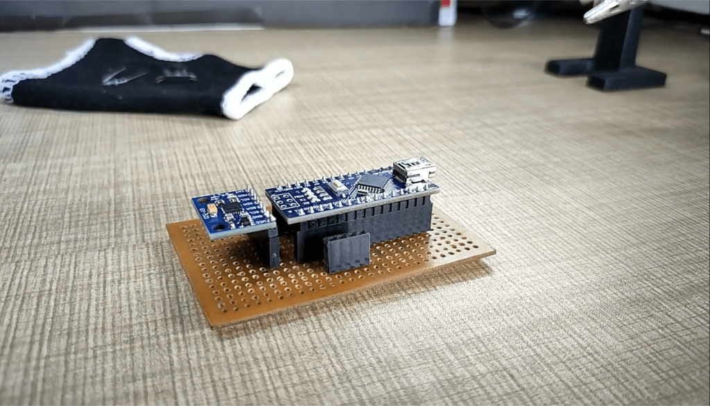
The transmitter section of this project consists of MPU6050 Gyroscope and Accelerometer , HC-05 Bluetooth Module, and Arduino Nano. The Arduino continuously gets data from the MPU6050 and sends this data to the Bluetooth. Bluetooth transmits the data into the environment.
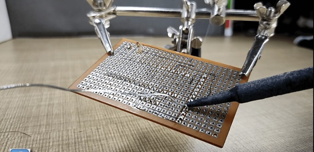
All components are soldering in the PCB board.
Receiver Circuit for Arduino Gesture Control Car
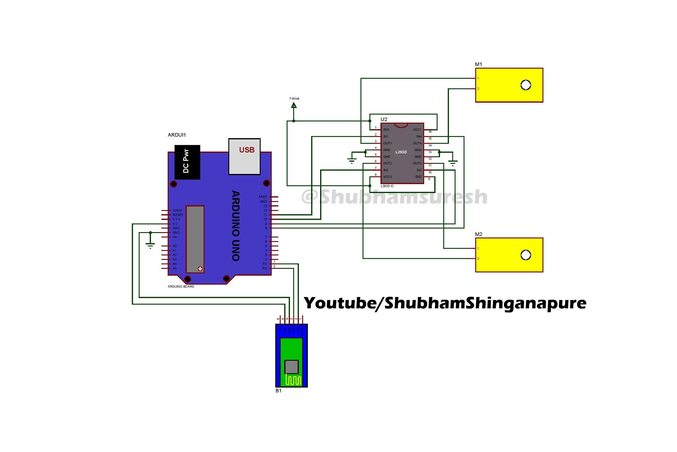
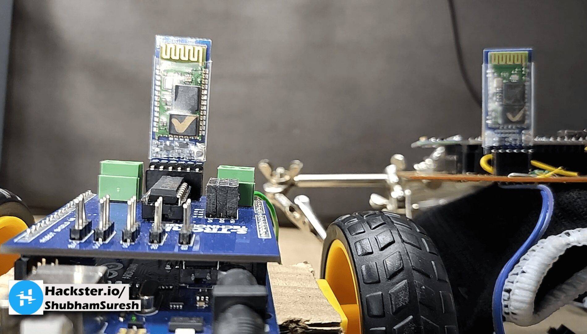
The receiver section of this gesture controlled robot consists of Arduino Nano, Bluetooth Module, 2 DC motors, and Motor driver shield. Bluetooth receives the data from the transmitter and sends it to Arduino nano. Then according to received signals, Arduino moves the DC motors. The circuit diagram is given below.
Contains
- Bluetooth module(slave):receiving data.
- Motor Shield: control direction and speed of motors.
- 9v battery to power the Arduino Nano and other components.
Assembling the Robot Chassis.
building the robot body
You can build the robot car body as shown in the Pictures
Software for Arduino Gesture Control Car
The software is fully depends on a library. So first download it. Click here to download.
After downloading extract the folder and then place it in the Arduino library folder.
Software for Transmitter:
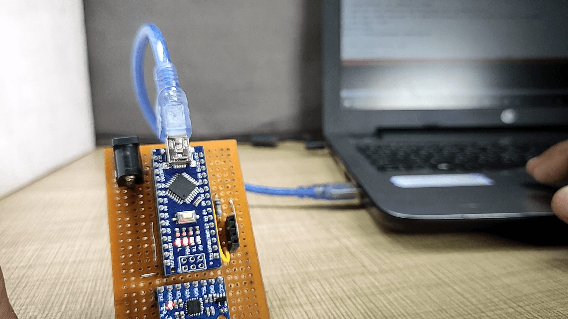
Before going to upload the Code to the transmitter board, you have to set few things in the Arduino IDE
1.Board -> Arduino Nano (what board you have used)
2.Serial Port -> COM90 (check the com port in which your device is connected )
After setting Done, Copy the below code and upload it.
|
1 2 3 4 5 6 7 8 9 10 11 12 13 14 15 16 17 18 19 20 21 22 23 24 25 26 27 28 29 30 31 32 33 34 35 36 37 38 39 40 41 42 43 44 45 46 47 48 49 50 51 52 53 54 55 56 57 58 59 60 61 62 63 64 65 66 67 68 69 70 71 72 73 74 75 76 77 78 79 80 81 82 83 84 85 86 87 88 89 90 91 92 93 94 95 96 97 98 99 100 101 102 103 104 105 106 107 108 109 110 111 112 113 114 115 116 117 118 119 120 121 122 123 124 125 126 127 128 129 130 131 132 133 134 135 136 137 138 139 140 141 142 143 144 145 146 147 148 149 150 151 152 153 154 155 156 157 158 159 160 161 162 163 164 165 166 167 168 169 170 171 172 173 174 175 176 177 178 179 180 181 182 183 184 185 186 187 188 189 190 191 192 193 194 195 196 197 198 199 200 201 202 203 204 205 206 |
//program modified on 3/10/19 by // by Shubham Shinganapure. // //for Gesture controled Robotic Car (remote ) #include "I2Cdev.h" #include "MPU6050_6Axis_MotionApps20.h" //#include "MPU6050.h" // not necessary if using MotionApps include file // Arduino Wire library is required if I2Cdev I2CDEV_ARDUINO_WIRE implementation // is used in I2Cdev.h #if I2CDEV_IMPLEMENTATION == I2CDEV_ARDUINO_WIRE #include "Wire.h" #endif // class default I2C address is 0x68 // specific I2C addresses may be passed as a parameter here // AD0 low = 0x68 (default for SparkFun breakout and InvenSense evaluation board) // AD0 high = 0x69 MPU6050 mpu; #define OUTPUT_READABLE_YAWPITCHROLL // MPU control/status vars bool dmpReady = false; // set true if DMP init was successful uint8_t mpuIntStatus; // holds actual interrupt status byte from MPU uint8_t devStatus; // return status after each device operation (0 = success, !0 = error) uint16_t packetSize; // expected DMP packet size (default is 42 bytes) uint16_t fifoCount; // count of all bytes currently in FIFO uint8_t fifoBuffer[64]; // FIFO storage buffer VectorFloat gravity; Quaternion q; float ypr[3]; // [yaw, pitch, roll] yaw/pitch/roll container and gravity vector uint8_t teapotPacket[14] = { '$', 0x02, 0,0, 0,0, 0,0, 0,0, 0x00, 0x00, '\r', '\n' }; volatile bool mpuInterrupt = false; // indicates whether MPU interrupt pin has gone high void dmpDataReady() { mpuInterrupt = true; } #include <SoftwareSerial.h> SoftwareSerial BTSerial(10, 11); // RX | TX int bt=8; int x =1; void setup() { #if I2CDEV_IMPLEMENTATION == I2CDEV_ARDUINO_WIRE Wire.begin(); TWBR = 24; // 400kHz I2C clock (200kHz if CPU is 8MHz) #elif I2CDEV_IMPLEMENTATION == I2CDEV_BUILTIN_FASTWIRE Fastwire::setup(400, true); #endif // initialize serial communication // (115200 chosen because it is required for Teapot Demo output, but it's // really up to you depending on your project) Serial.begin(115200); BTSerial.begin(38400); // while (!Serial); // wait for Leonardo enumeration, others continue immediately Serial.println(F("Initializing I2C devices...")); mpu.initialize(); // verify connection Serial.println(F("Testing device connections...")); Serial.println(mpu.testConnection() ? F("MPU6050 connection successful") : F("MPU6050 connection failed")); // wait for ready // load and configure the DMP Serial.println(F("Initializing DMP...")); devStatus = mpu.dmpInitialize(); // supply your own gyro offsets here, scaled for min sensitivity mpu.setXGyroOffset(220); mpu.setYGyroOffset(76); mpu.setZGyroOffset(-85); mpu.setZAccelOffset(1788); // make sure it worked (returns 0 if so) if (devStatus == 0) { // turn on the DMP, now that it's ready Serial.println(F("Enabling DMP...")); mpu.setDMPEnabled(true); // enable Arduino interrupt detection Serial.println(F("Enabling interrupt detection (Arduino external interrupt 0)...")); attachInterrupt(0, dmpDataReady, RISING); mpuIntStatus = mpu.getIntStatus(); // set our DMP Ready flag so the main loop() function knows it's okay to use it Serial.println(F("DMP ready! Waiting for first interrupt...")); dmpReady = true; // get expected DMP packet size for later comparison packetSize = mpu.dmpGetFIFOPacketSize(); } else { // ERROR! // 1 = initial memory load failed // 2 = DMP configuration updates failed // (if it's going to break, usually the code will be 1) Serial.print(F("DMP Initialization failed (code ")); Serial.print(devStatus); Serial.println(F(")")); } // configure LED for output pinMode(bt,INPUT); } // ================================================================ // === MAIN PROGRAM LOOP === // ================================================================ void loop() { if(digitalRead(bt)==HIGH) { x++; delay(150); } if((x%2)==0){ // if programming failed, don't try to do anything if (!dmpReady) return; // wait for MPU interrupt or extra packet(s) available while (!mpuInterrupt && fifoCount < packetSize) { // other program behavior stuff here // . // . // . // if you are really paranoid you can frequently test in between other // stuff to see if mpuInterrupt is true, and if so, "break;" from the // while() loop to immediately process the MPU data // . // . // . } // reset interrupt flag and get INT_STATUS byte mpuInterrupt = false; mpuIntStatus = mpu.getIntStatus(); // get current FIFO count fifoCount = mpu.getFIFOCount(); // check for overflow (this should never happen unless our code is too inefficient) if ((mpuIntStatus & 0x10) || fifoCount == 1024) { // reset so we can continue cleanly mpu.resetFIFO(); Serial.println(F("FIFO overflow!")); // otherwise, check for DMP data ready interrupt (this should happen frequently) } else if (mpuIntStatus & 0x02) { // wait for correct available data length, should be a VERY short wait while (fifoCount < packetSize) fifoCount = mpu.getFIFOCount(); // read a packet from FIFO mpu.getFIFOBytes(fifoBuffer, packetSize); // track FIFO count here in case there is > 1 packet available // (this lets us immediately read more without waiting for an interrupt) fifoCount -= packetSize; #ifdef OUTPUT_READABLE_YAWPITCHROLL // display Euler angles in degrees mpu.dmpGetQuaternion(&q, fifoBuffer); mpu.dmpGetGravity(&gravity, &q); mpu.dmpGetYawPitchRoll(ypr, &q, &gravity); Serial.print("ypr\t"); Serial.print(ypr[0] * 180/M_PI); Serial.print("\t"); Serial.print(ypr[1] * 180/M_PI); Serial.print("\t"); Serial.println(ypr[2] * 180/M_PI); if((ypr[1] * 180/M_PI)<= -25) {BTSerial.write('F'); } else if((ypr[1] * 180/M_PI)>= 25) {BTSerial.write('B'); } else if((ypr[2] * 180/M_PI)<= -25) {BTSerial.write('L'); } else if((ypr[2] * 180/M_PI)>= 20) {BTSerial.write('R'); } else{ BTSerial.write('S'); } #endif } } else{ BTSerial.write('S'); } }<br /><br /> |
Software for Receiver :
Similar to the above set the following for receiver board
|
1 2 3 4 5 6 7 8 9 10 11 12 13 14 15 16 17 18 19 20 21 22 23 24 25 26 27 28 29 30 31 32 33 34 35 36 37 38 39 40 41 42 43 44 45 46 47 48 49 50 51 52 53 54 55 56 57 58 59 60 61 62 63 64 65 66 67 68 69 70 71 72 73 74 75 76 77 78 79 80 81 82 83 84 85 86 87 |
// //for Gesture controled Robotic Car int lm1=8; //left motor output 1 int lm2=9; //left motor output 2 int rm1=10; //right motor output 1 int rm2=11; //right motor output 2 char d=0; void setup() { pinMode(lm1,OUTPUT); pinMode(lm2,OUTPUT); pinMode(rm1,OUTPUT); pinMode(rm2,OUTPUT); Serial.begin(38400); sTOP(); } void loop() { if(Serial.available()>0) { d=Serial.read(); if(d=='F') { ForWard(); } if(d=='B') { BackWard(); } if(d=='L') { Left(); } if(d=='R') { Right(); } if(d=='S') { sTOP(); } } } void ForWard() { digitalWrite(lm1,HIGH); digitalWrite(lm2,LOW); digitalWrite(rm1,HIGH); digitalWrite(rm2,LOW); } void BackWard() { digitalWrite(lm1,LOW); digitalWrite(lm2,HIGH); digitalWrite(rm1,LOW); digitalWrite(rm2,HIGH); } void Left() { digitalWrite(lm1,LOW); digitalWrite(lm2,HIGH); digitalWrite(rm1,HIGH); digitalWrite(rm2,LOW); } void Right() { digitalWrite(lm1,HIGH); digitalWrite(lm2,LOW); digitalWrite(rm1,LOW); digitalWrite(rm2,HIGH); } void sTOP() { digitalWrite(lm1,LOW); digitalWrite(lm2,LOW); digitalWrite(rm1,LOW); digitalWrite(rm2,LOW); } |
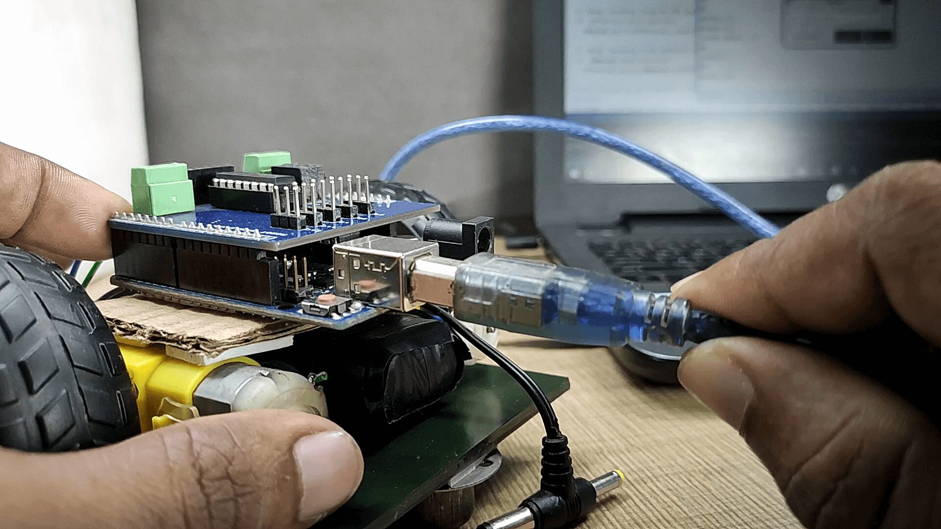
- Remove the Usb cable from both the board
- Provide external power (battery ) to the both the board.( positive terminal goes to Vin )
Follow This Instruction Easiest Way to Make a Arduino Gesture Control Robot
Video
Let’s Power it and Enjoy Like a super Hero
Hope you find this useful. if yes, like it, share it, comment your doubt.
Thank you!



2 Comments
Pingback: Make Arduino Home automation System Using TV Remote
Pingback: What Is Sensor? Different Types Of Sensor - Explained 2022.