
Here you’ll learn how to use an NPK soil sensor with Arduino to measure the nutrient levels in your soil! This guide will teach you how to build a circuit and write code to get readings from the sensor.
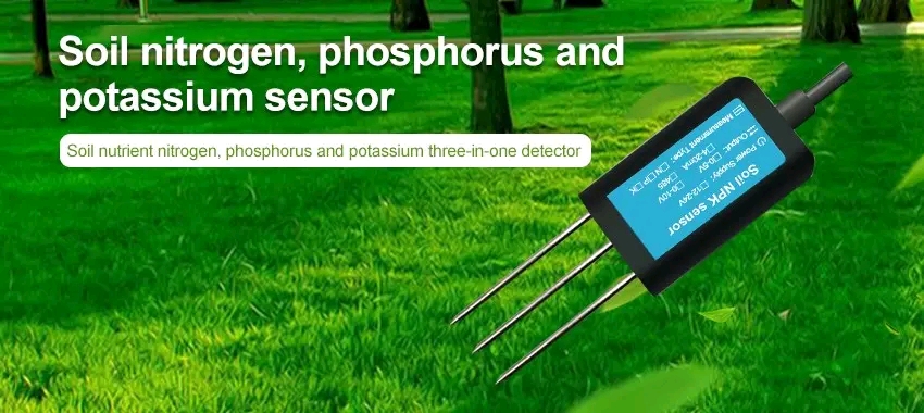
NPK sensor is a device for measuring the levels of three important minerals in plants: nitrogen (N), phosphorus (P), and potassium (K). These soil nutrients drive plant health and vegetative growth. This guide shows you how to use NPK soil sensors with Arduino.
Required Materials
To Interface the NPK soil sensor with Arduino, you will need:
- Arduino Uno board
- NPK soil sensor kit
- Jumper wires
- Breadboard
- USB cable
What is soil NPK?
Just as sugar, fat, and protein are the three major nutrients required for human and animal fitness, nitrogen, phosphorus, and potassium are the three main nutrients required for plant production. These nutrients play important roles in different parts of plant growth, from leaf growth, etc.
Other important elements that plants need in smaller amounts include calcium, magnesium, sulfur, iron, manganese, zinc, copper, boron, molybdenum, chlorine, and nickel.
- Nitrogen is important for leaf growth and good green color.
- Phosphorus helps with root formation and seed production.
- Potassium promotes healthy branches and overall plant growth.
Maintaining proper levels of these three nutrients in the soil is important for healthy plant growth and good results. NPK sensors are one tool that can help farmers and other agricultural professionals measure the levels of these nutrients in the soil and adjust fertilization practices accordingly.
Nitrogen
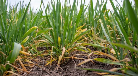
Plants lacking nitrogen may exhibit yellowing of leaves, stunted growth, delayed flowering, and reduced fruit and seed production. This is because nitrogen is an important element that is required for plant growth.
Phosphorus
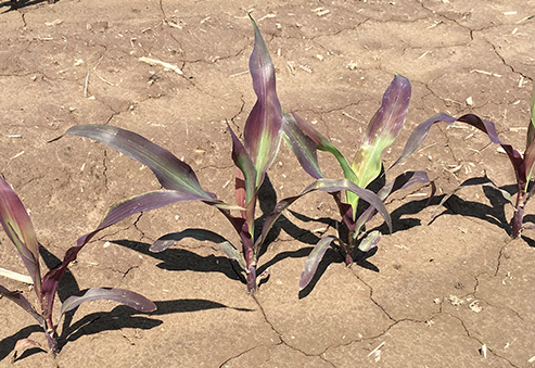
Plants lacking phosphorus may show a range of signs, like growth, poor root development, and dark green or purple leaves. This is because phosphorus is an important nutrient that is required for plant growth and development, and is especially important for root growth and flowering. Without sufficient phosphorus, plants may suffer from growing healthy root systems and may have problems taking up other nutrients from the soil.
Potassium
Plants lacking potassium may have restricted growth, weak branches, yellowing or browning of leaf margins, and decreased resistance and disease. This is because potassium is an important nutrient that is required for water regulation, photosynthesis, and protein synthesis.


What is an NPK sensor and how it works
An NPK sensor is a device that measures the levels of nitrogen (N), phosphorus (P), and potassium (K) in soil. These three nutrients are the main ingredients of fertilizers and help plants grow faster.
The sensor works by passing an electric current through the sample, and the resulting electrical resistance is used to calculate the concentrations of each element. the sensor is able to calculate the concentration of each element in the sample.
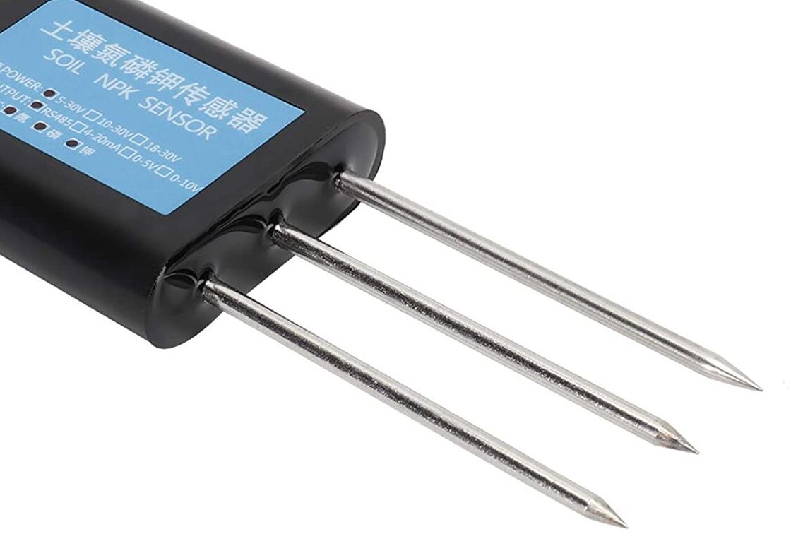
The JXCT Soil NPK sensor operates on a voltage range of 9-24V and has low power consumption. With a high-resolution capacity of up to 1 mg/kg (mg/l), the sensor can accurately measure the concentration of nitrogen, phosphorus, and potassium in the soil, allowing farmers and agricultural professionals to make informed decisions about fertilization and nutrient management.
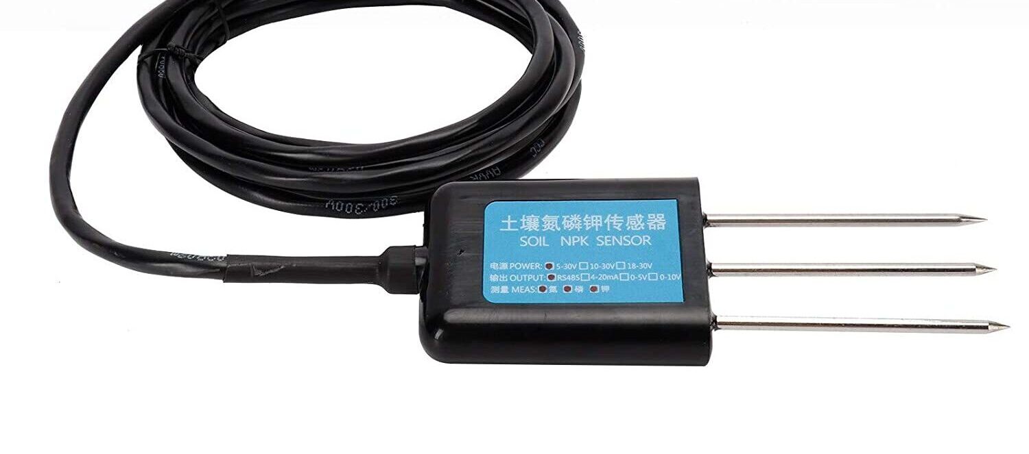
The soil NPK sensor is provided stainless steel probe that is designed to be rust-resistant, electric, and salt-resistant. This makes the sensor suitable for nearly all soil, including alkaline soil, acid soil, substrate soil, and seedling bed soil.
Soil NPK sensor Pinout
The figure below displays the pinout for the sensor.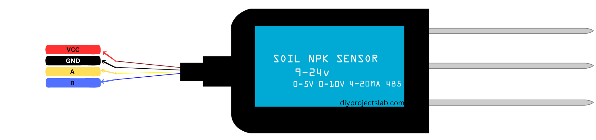
- VCC pin: is used to connect to a voltage supply ranging from 5V to 30V.
- A pin: is a differential signal that should be connected to the A pin of the MAX485 Modbus Module.
- B pin: is another differential signal that should be connected to the B pin of the MAX485 Modbus Module.
- Ground pin (GND): should be connected to the ground.
Soil NPK sensor features
A Soil NPK (Nitrogen, Phosphorus, Potassium) sensor typically features the following:
Probes: The sensor normally has multiple probes that are inserted into the soil to gather data.
NPK measurement: The sensor can detect the levels of Nitrogen, Phosphorus, and Potassium in the soil, which are essential nutrients for plant growth.
Real-time monitoring: The sensor constantly monitors the nutrient levels in the soil, which allow farmers to adjust their fertilization methods in real-time.
Waterproof: The sensors are built to be weatherproof against extreme weather conditions and can operate even in harsh temperatures or rainfall.
Soil NPK sensor Specs
Here are the specifications for Soil NPK Sensor:
- Operating voltage: DC 9-30V
- Power consumption: less than 20mA
- Measurement range: 0-9.99 mg/L
- Baud Rate: 2400/4800/9600
- Measurement accuracy: ±10% or ±0.1 mg/L (whichever is greater)
- Resolution: 1mg/kg
- Precision: ±2%FS
- Measurement time: 2-3 seconds
- Output signal: RS485 (Modbus protocol)
- Probe material: stainless steel
- Protection class: IP68
- Probe length: 70mm
- Probe diameter: 12mm
- Cable length: 3m
- Operating temperature: 0-50°C
- Operating humidity: 5-90% RH
- Weight: 150g
Note: Soil NPK sensor can measure nitrogen, phosphorus, and potassium with a resolution of up to 1 mg/kg (mg/l).
NPK sensor Application
The Soil NPK sensor can be used in a type of applications, including:
- Agriculture
- Environmental monitoring
- Horticulture
- Soil testing laboratories
- Education
Check out the NPK sensor datasheet for more information.
MAX485 TTL to RS-485 Module TTL to RS485 Converter
The MAX485 TTL to RS-485 module is a reliable, low-cost interface for connecting TTL-level devices to RS-485 networks. It is based on the MAX485 IC, which is a low-power transceiver for RS-485 communication. The module features a 5V power supply and can operate at speeds up to 2.5 Mbps.
Specs MAX485 TTL to RS-485 Module
- Compatible with Arduino
- Supports half-duplex communication mode
- 5V operation
- Supports multiple data rates up to 2.5 Mbps
- Long-distance communication up to 1200 meters
- Compact size and easy to use
- Supports multiple interface standards such as EIA/TIA-485 and ISO 8482:1987(E)
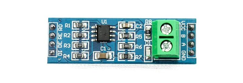
Pinout MAX485 TTL to RS-485 Module
Data side
- RO = TTL Data Output (connects to Arduino RX pin)
- RE = Receiver Enable. Generally joint to DE Pin.
- DE = Driver Enable. Generally joint to RE Pin.
- DI = TTL Data Input (connects to microcontroller TX pin)
Output side
- VCC = 5V
- B = RS-485 differential data signal B
- A = RS-485 differential data signal A
- GND = Ground
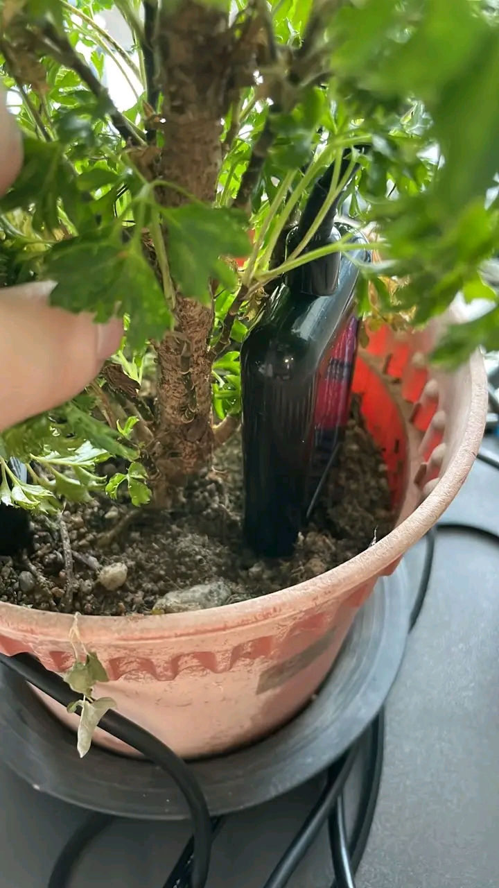
Interfacing NPK Soil Sensor With Arduino
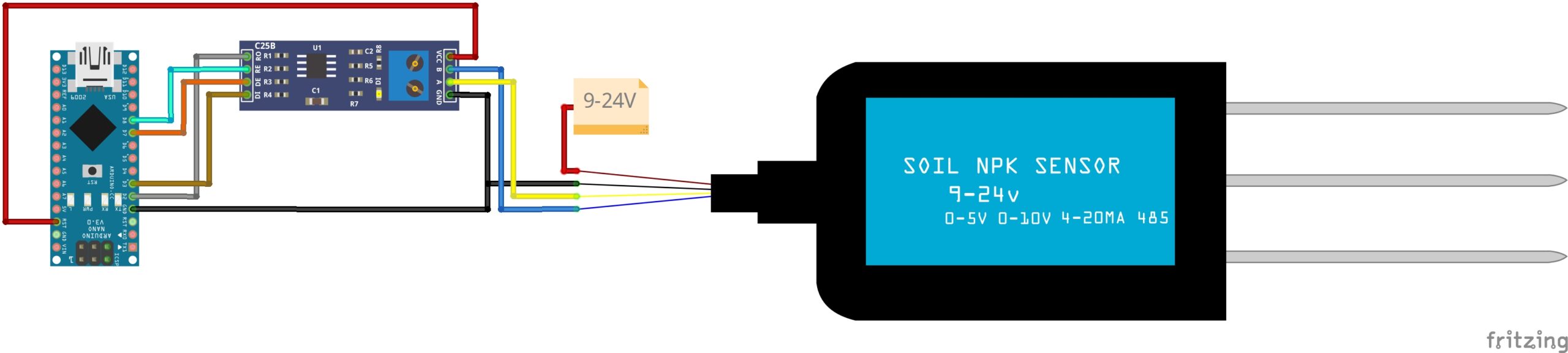
To connect the NPK sensor to an Arduino, first, connect the R0 & DI pins from the Modbus to the D2 & D3 pins of the Arduino using Software Serial.
Then, connect the DE & RE pins of the Modbus to the D7 & D8 pins of the Arduino to enable DE & RE high. The NPK sensor has 4 wires, the brown wire is for VCC, which requires a 9V-24V power supply. Connect the black wire to the GND of the Arduino.
The blue wire (B pin) should be connected to the B pin of MAX485 and the yellow wire (A pin) should be connected to the A pin of MAX485.
| Soil NPK Sensor | MAX485 | Arduino |
|---|---|---|
| VCC (9V-24V) | – | External Power Supply |
| GND | GND | Ground |
| B | MAX485 B | |
| A | MAX485 A | |
| Modbus RX | D2 | |
| Modbus TX | D3 | |
| RS485 DE | D7 | |
| RS485 RE | D8 |
Modbus Command for NPK Sensor
To send a command to an NPK sensor over a Modbus/RS485 network, you need to know the sensor’s Modbus address code. This address code tells you which registers store the sensor’s data and how to access the data. NPK sensors usually use Modbus RTU protocol over RS485 for communication.
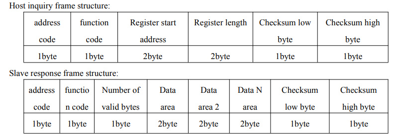
The Modbus-RTU communication protocol follows a specific format that includes the following elements:
- Initial structure: ≥ 4 bytes of tim
- Address code: 1 byte (default value is 0x01)
- Function code: 1 byte
- Data area: N bytes
- Error check: 16-bit CRC
- Ending structure ≥ 4 bytes
Host inquiry frame structure:
NPK Sensor Communication protocol example and explanation
There are three different inquiry frames that can be used to read the values of Nitrogen (N), Phosphorous (P), and Potassium (K) from the NPK Sensor, These inquiry frames are detailed for each element and are provided in the instruction manual for the NPK Sensor.
Example 1: Read the real-time value of nitrogen content at device address 0x01
Inquiry frame
| address code |
Function Code | Starting Address | Data Length | Checksum (Low Byte) | Checksum (High Byte) |
|---|---|---|---|---|---|
| 0x01 | 0x03 | 0x00 0x1E | 0x00 0x01 | 0xE4 | 0x0C |
Response frame
| address code |
Function Code | Returns the nu number of valid bytes |
Data Length | Checksum (Low Byte) | Checksum (High Byte) |
|---|---|---|---|---|---|
| 0x01 | 0x03 | 0x02 | 0x00 0x20 | 0xB9 | 0x9C |
Calculation of nitrogen content :
Nitrogen content: 0020 H (hexadecimal) = 32 => nitrogen = 32mg / kg
For Calculating the nitrogen range in the soil using the Modbus command from the NPK sensor, you first need to read the hexadecimal value of the nitrogen parameter from the sensor. In this case, the value is 0020 H.
Example 2: Read the real-time value of phosphorus content at device address 0x01
| address code |
Function Code | Starting Address | Data Length | Checksum (Low Byte) | Checksum (High Byte) |
|---|---|---|---|---|---|
| 0x01 | 0x03 | 0x00 0x1F | 0x00 0x01 | 0xB5 | 0xCC |
Response frame
| address code |
Function Code | Returns the nu number of valid bytes |
Data Length | Checksum (Low Byte) | Checksum (High Byte) |
|---|---|---|---|---|---|
| 0x01 | 0x03 | 0x02 | 0x00 0x25 | 0x79 | 0x9F |
Calculation of phosphorus content:
Phosphorus content: 0025 H (hexadecimal) = 37 => phosphorus = 37mg / kg
Example 3: Read the real-time value of potassium content at device address 0x01
| address code |
Function Code | Starting Address | Data Length | Checksum (Low Byte) | Checksum (High Byte) |
|---|---|---|---|---|---|
| 0x01 | 0x03 | 0x00 0x20 | 0x00 0x01 | 0x85 | 0xC0 |
Response frame
| address code |
Function Code | Returns the nu number of valid bytes |
Data Length | Checksum (Low Byte) | Checksum (High Byte) |
|---|---|---|---|---|---|
| 0x01 | 0x03 | 0x02 | 0x00 0x30 | 0xB8 | 0x50 |
Calculation of potassium content:
Potassium content: 0030 H (hexadecimal) = 48 => potassium = 48mg / kg
NPK content in the soil
- 0020 H(hexadecimal )=32=>Nitrogen=32mg/kg
- 0025 H(hexadecimal )=37=>Phosphorus=37mg/kg
- 0030 H(hexadecimal )=48=>Potassium=48mg/kg
Arduino NPK Sensor Reading Code
|
1 2 3 4 5 6 7 8 9 10 11 12 13 14 15 16 17 18 19 20 21 22 23 24 25 26 27 28 29 30 31 32 33 34 35 36 37 38 39 40 41 42 43 44 45 46 47 48 49 50 51 52 53 54 55 56 57 58 59 60 61 62 63 64 65 66 67 68 69 70 71 72 73 74 75 76 77 78 79 80 |
#include <SoftwareSerial.h> #include <Wire.h> // Define RS485 pins for RE and DE to switch between transmit and receive mode #define RS485_RE 8 #define RS485_DE 7 // Modbus RTU requests for reading NPK values const byte nitro[] = {0x01, 0x03, 0x00, 0x1e, 0x00, 0x01, 0xe4, 0x0c}; const byte phos[] = {0x01, 0x03, 0x00, 0x1f, 0x00, 0x01, 0xb5, 0xcc}; const byte pota[] = {0x01, 0x03, 0x00, 0x20, 0x00, 0x01, 0x85, 0xc0}; // A byte array to store NPK values byte values[11]; // SoftwareSerial object to communicate with the RS485 module SoftwareSerial modbus(2, 3); // RX, TX void setup() { // Start serial communication with the computer Serial.begin(9600); // Start serial communication with the RS485 module modbus.begin(9600); // Set RS485 pins as outputs pinMode(RS485_RE, OUTPUT); pinMode(RS485_DE, OUTPUT); // Turn off RS485 receiver and transmitter initially digitalWrite(RS485_RE, LOW); digitalWrite(RS485_DE, LOW); // Wait for the RS485 module to initialize delay(500); } void loop() { // Read NPK values and print them to the serial monitor Serial.print("Nitrogen: "); Serial.print(readValue(nitro)); Serial.println(" mg/kg"); Serial.print("Phosphorous: "); Serial.print(readValue(phos)); Serial.println(" mg/kg"); Serial.print("Potassium: "); Serial.print(readValue(pota)); Serial.println(" mg/kg"); // Wait for 2 seconds before reading values again delay(2000); } // Sends a Modbus RTU request and reads the response to get a value byte readValue(const byte* request) { // Set RS485 module to transmit mode digitalWrite(RS485_RE, HIGH); digitalWrite(RS485_DE, HIGH); // Send Modbus RTU request to the device modbus.write(request, sizeof(request)); // Set RS485 module to receive mode digitalWrite(RS485_RE, LOW); digitalWrite(RS485_DE, LOW); // Wait for the response to be received delay(10); // Read the response into the values array byte responseLength = modbus.available(); for (byte i = 0; i < responseLength; i++) { values[i] = modbus.read(); } // Return the value from the response return values[3] << 8 | values[4]; } |
Conclusion
By following this complete tutorial, you have learned how to use NPK Soil Sensor With Arduino and test an NPK soil sensor. This sensor can help you identify soil needs in your yard and garden.
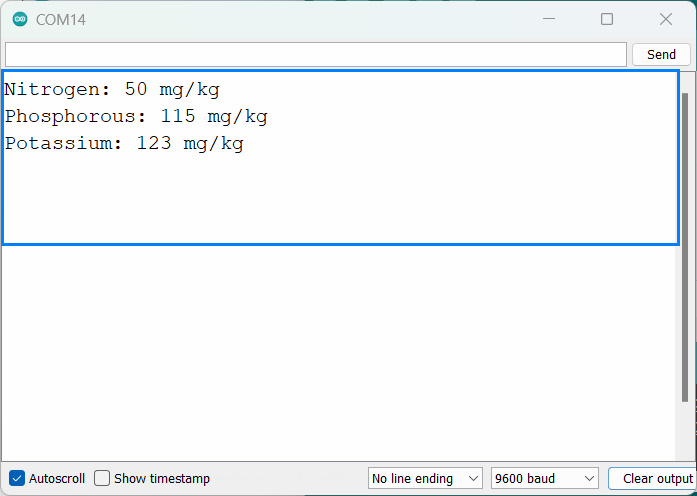
The output from the Arduino
Nitrogen: 50 mg/kg
Phosphorous: 115 mg/kg
Potassium: 123 mg/kg
Nitrogen: 52 mg/kg
Phosphorous: 114 mg/kg
Potassium: 120 mg/kg
Nitrogen: 57 mg/kg
Phosphorous: 119 mg/kg
Potassium: 123 mg/kg


2 Comments
This code is giving me the output
Potassium: 0 mg/kg
Nitrogen: 0 mg/kg
Phosphorous: 0 mg/kg
Potassium: 0 mg/kg
If it’s only measuring the conductivity (mathematical inverse of resistance) in the soil then there is no way it can tell the difference between the 3 nutrients and any other conductive element. The soil may be high in iron or copper just as easily. It would seem more honest to just provide the EC (electrical conductance) value than to gaslight people with fictitious specific values of each nutrient. I’d like to see test separate results with this probe sitting in a solution of nitrogen-only, phosphorus-only, and potassium-only enriched water to see if the proportions of the individual NPK “readings” are always the same as I suspect.