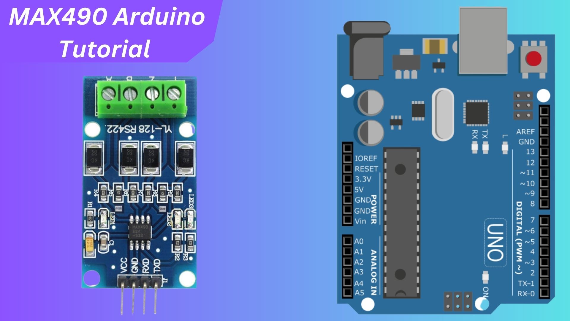
This tutorial will explain how to Interface RS-422 To TTL MAX490 Convertor With Arduino device to an Arduino. MAX490 RS-422 to TTL Converter is a board that enables devices using RS-422 and TTL protocols, which operate at different voltage levels, to communicate with each other. By connecting the MAX490 module to an Arduino board, we can enable the Arduino to communicate with RS-422 devices over long distances.
MAX490 converts the RS-422 signals to TTL-compatible levels, allowing the RS-422 device to be connected to a TTL device.
The RS-422 protocol was developed to solve the distance limitations of the RS-232 protocol. RS-232 can only transmit data over 15 meters (50 feet). short distances, while RS-422 allows for longer distances of up to 1,200 meters (3,900 ft).
Required Material
- Arduino Uno
- RS-422 to TTL Converter Module
- Breadboard
- Jumper wires
RS-422 to TTL Converter Module
The MAX490 RS422 to Serial TTL Module is designed to extend the range of TTL serial communications between devices beyond the typical limit of 10 meters. It utilizes the Maxim MAX490 chip to convert signals between Serial and RS-422 protocols. By using the RS-422 protocol, it can achieve a maximum communications distance of 1000 meters. checkout Complete Guide for NPK Soil Sensor with Arduino Tutorial
It has protection features, termination resistors, power/data indicators, and supports 5V logic signals. to use it with an Arduino, just simply connect the module, write code, and chat with the Serial Monitor of the Arduino program.
The protocol is full-duplex but only supports one sending device at each end of the bus. If you need to connect more devices, it is recommended to use the RS-485 protocol, such as the one used by the MAX485 module.
Specification
- Operating Voltage: 5V DC
- Chip: MAX490
- Interface: UART TTL Serial Microcontroller Interface
- Protocol: RS422
- Communication Type: Full-Duplex
- Maximum Communication Distance: 1000 meters
- Maximum Speed: 2.5 Mbps
- Maximum Emitter: 1
- Maximum Receiver: 32
- Size: 50 x 27 mm
Application
- Industrial Automation
- Long-Distance Communication
- Security Systems
- Robotics and Motion Control
- Smart Energy Management
Pinout
MAX490 vs MAX485
The MAX490 and MAX485 are both popular transceiver chips designed for serial communication. Since there are significant differences between the two ICs in terms of functionality and specifications, it is important to know which IC to use for a particular application. Here’s a comparison between the MAX490 and MAX485:
- Communication:
- MAX490: RS-485/RS-422 Protocol.
- MAX485: Designed for RS-485 Protocol.
- Half-Duplex/Full-Duplex:
- MAX490: Full-duplex communication
- MAX485: Supports half-duplex communication
- Driver and Receiver Enable:
- MAX490: Separate DE and RE pins to control the transmit/receive mode.
- MAX485: Single DE/RE pin
- Maximum Data Rate:
- MAX490: Maximum data rate of 2.5 Mbps.
- MAX485: 10 Mbit/s (at 12 meters)
- ESD Protection:
- MAX490: Provides ESD (Electrostatic discharges) protection, usually around 15KV.
- MAX485: No ESD (Electrostatic discharges) protection
- Power Supply Voltage:
- MAX490: Operates at 5V DC.
- MAX485: Operates at 5V and 3.3V.
Interfacing RS-422 TO TTL MAX490 Convertor With Arduino
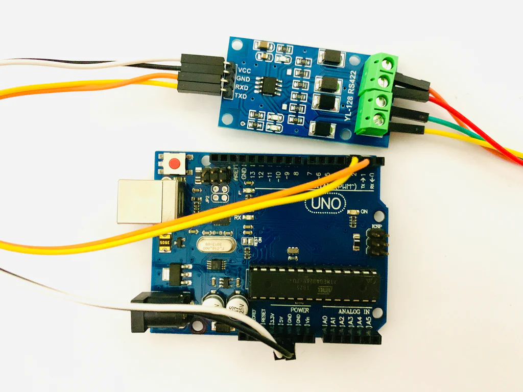
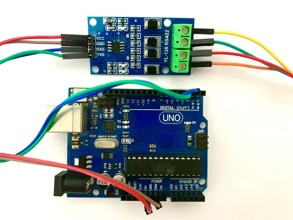
Here’s the simple connection diagram for connecting an Arduino to the MAX490 RS-422 transceiver and the buttons:
- Arduino RX pin to pin 2 of the MAX490.
- Arduino TX pin to pin 3 of the MAX490.
- Button for turning on the LED to Arduino pin 4.
- Button for turning off the LED to Arduino pin 5.
Add an LED to the Slave
- LED to Arduino pin 4.
This setup allows you to control the LED on pin 4 of the Slave Arduino based on commands received from the Master Arduino through RS-422 communication.
The connection between the two modules should be made with two pairs of twisted cables following the connections.
- “Y” output of one module to the “A” input of the other module.
- “Z” output of one module to the “B” input of the other module.
- “A” output of one module to the “Y” input of the other module.
- “B” output of one module to the “Z” input of the other module.
The Connection between the modules should be YA, ZB, AY, and BZ.
Source Code
Make sure to upload the Master code to the Master Arduino and the Slave code to the Slave Arduino. This will enable communication between the two Arduinos using the specified protocol and control the LED accordingly.
Master Arduino Code
The Master Arduino code is responsible for sending commands to the Slave Arduino to control an LED based on button presses.
|
1 2 3 4 5 6 7 8 9 10 11 12 13 14 15 16 17 18 19 20 21 22 23 24 25 26 27 28 29 30 31 32 33 34 35 36 37 38 39 |
/* Communication between two Arduino boards Master Arduino Connection: - Y-A, Z-B, A-Y, B-Z. */ #include <SoftwareSerial.h> SoftwareSerial rs422(2, 3); // RX, TX #define btn_on 4 #define btn_off 5 // PROTOCOL DEFINITION #define TURN_ON "TURN_ON" #define TURN_OFF "TURN_OFF" void setup() { rs422.begin(9600); // Initialize software serial communication pinMode(btn_on, INPUT_PULLUP); pinMode(btn_off, INPUT_PULLUP); } void loop() { if (!digitalRead(btn_on)) { while (!digitalRead(btn_on)) { delay(20); // Debounce button press } // Send the protocol to turn on the LED rs422.print(TURN_ON); } else if (!digitalRead(btn_off)) { while (!digitalRead(btn_off)) { delay(20); // Debounce button press } // Send the protocol to turn off the LED rs422.print(TURN_OFF); } } |
Slave Arduino Code:
The Slave Arduino code receives commands from the Master Arduino and controls an LED accordingly.
|
1 2 3 4 5 6 7 8 9 10 11 12 13 14 15 16 17 18 19 20 21 22 23 24 25 26 27 28 29 30 31 32 33 34 35 36 37 38 39 40 |
/* Communication between two Arduino boards Slave Arduino Connection: - Y-A, Z-B, A-Y, B-Z. */ #include <SoftwareSerial.h> #include <string.h> SoftwareSerial rs422(2, 3); // RX, TX #define led 4 // PROTOCOL DEFINITION #define TURN_ON "TURN_ON" #define TURN_OFF "TURN_OFF" String protocol = ""; void setup() { rs422.begin(9600); pinMode(led, OUTPUT); Serial.begin(9600); } void loop() { if (rs422.available()) { protocol += char(rs422.read()); if (protocol == TURN_ON) { digitalWrite(led, HIGH); // Clear the protocol protocol = ""; } if (protocol == TURN_OFF) { digitalWrite(led, LOW); // Clear the protocol protocol = ""; } } } |
Conclusion
In conclusion, the provided code shows a basic communication setup between two MAX490 Convertors with Arduino, where one acts as the Master and the other as the Slave.
The Master Arduino sends commands based on button presses, while the Slave Arduino receives and processes these commands to control an LED.

