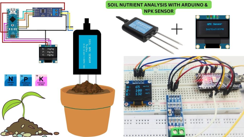
This tutorial uses Arduino and NPK sensors to measure soil nutrients in real-time. The sensor is placed in the soil and Sensor is connected to Arduino. NPK Sensor measures the soil nutrients and sends the data to the Arduino. then the data is displayed on the OLED Display, and the data is used to adjust the watering and fertilization schedule accordingly. Here’s a step-by-step guide to help you get started:
This system can be used in large agricultural fields or in small-scale gardens.
Required Material
Before you start, you’ll need the following materials:
- Arduino Nano board
- Soil NPK sensor
- MAX485 TTL to RS-485 Interface Module
- 0.96″ SSD1306 OLED Display
- Jumper wires
- Breadboard (optional)
- 9V-24V Power Supply
Overview of the Arduino and NPK sensor
An NPK sensor is a device that measures the levels of three essential nutrients in the soil – nitrogen (N), phosphorus (P), and potassium (K).
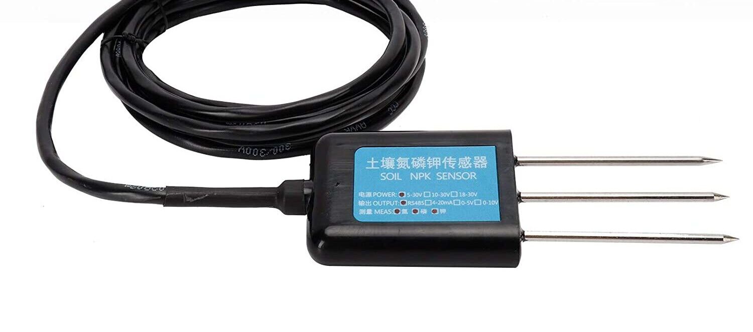
By using an NPK sensor, growers can adjust their fertilizer application to maintain the optimal nutrient levels for their crops.
Pinout NPK Sensor
 Specifications NPK Sensor
- Power supply: 9 to 24V DC
- Maximum power consumption: ≤0.15W
- Operating temperature: -40~80℃
- NPK parameters: Range: 0-1999 mg/kg(mg/L)
- Resolution: 1 mg/kg(mg/L)
- Precision: ±2%FS
- Response time: ≤1S
- Protection grade: IP68
- Probe material: 316 stainless steel
- Sealing material: Black flame
- Default cable length: 2-3 meters
- Dimensions: 45*15*123mm
- Output signal: RS485
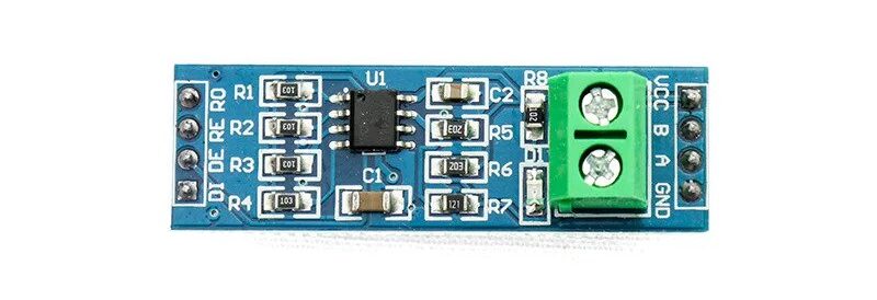
MAX485 RS485 Transceiver Module
RS-485 is standard for serial communication transmission of data over long distances, and it has many advantages over other serial protocols such as RS-232. It is capable of transmitting data up to a distance of 1200 meters. The use of MAX485 ensures a reliable and noise-free transmission of data, which is necessary for the accurate sensing of NPK levels.
In the case of an NPK (Nitrogen, Phosphorus, Potassium) sensor, the use of MAX485 allows for the sensor to communicate over long distances using a microcontroller or computer.
This module provides reliable and constant communication over long distances, which is necessary for accurate and consistent sensing of NPK levels in agricultural or environmental monitoring applications.
Pinout of MAX485 RS485 Transceiver
The first 4-pin header on the module’s data side includes four pins: RO, RE, DE, and DI.
- RO (Receiver Output)
- RE (Receiver Enable)
- DE (Driver Enable)
- DI (Driver Input)
The second 4-pin header on the output side includes four pins: VCC, B, A, and GND.
- VCC
- B pin is the inverted data line
- A pin is the non-inverted data line
- GND
The 1 x 2 screw terminal block on the output side has two pins: B and A.
- B pin is the inverted data line
- A pin is the non-inverted data line
Features MAX485 RS485 Transceiver
- Operating voltage: 5V
- Maximum data rate: 2.5Mbps
- Maximum distance: 1200 meters (at lower data rates)
- Operating temperature range: -40°C to +85°C
- Number of channels: 1
- Supply current: 300 uA (typical)
- Package type: 8-pin DIP or SOIC
Connect NPK Sensor & OLED to Arduino
The wiring connections between the Arduino and the RS485 module should be as follows:
Connect the components as per the circuit diagram provided. The soil NPK sensor has four wires, the brown one is VCC, the black one is GND, the blue wire is the B pin, and the yellow wire is the A pin.
Connect the DE and RE pins of the MAX485 module to D7 and D8 of the Arduino.
VCC and GND pins of the OLED display to the 3.3V and GND of the Arduino respectively.
SDA and SCL pins of the OLED display to the A4 and A5 of the Arduino respectively.
Arduino -> RS485 module
- 5V -> VCC
- GND -> GND
- Pin 2 -> RO
- Pin 3 -> DI
- Pin 7 ->DE
- Pin 8 ->RE
RS485 module -> Soil NPK Sensor
- Ground to Ground
- VCC pin to 5V of the Arduino
- B -> Blue wire
- A-> Yellow wire
Arduino -> OLED
- 5v -> VCC
- GND -> GND
- SCL -> A5
- SDA -> A4
Code & Libraries
When the connection is successfully connected please download both libraries from the link below. Check my previous post for an explanation of how to collect data from NPK sensor using the Arduino
Download required Library
- Adafruit SSD1306 – Adafruit_SSD1306.h
- Adafruit GFX Library – Adafruit_GFX.h
Upload the code to the Arduino Nano board.
This code is only capable of measuring Soil NPK values up to 255mg/kg due to reading only 8-bit values, and the sensor can measure up to 1999mg/kg reading with 16-bit data, you need to modify the code to read 16-bit data.
|
1 2 3 4 5 6 7 8 9 10 11 12 13 14 15 16 17 18 19 20 21 22 23 24 25 26 27 28 29 30 31 32 33 34 35 36 37 38 39 40 41 42 43 44 45 46 47 48 49 50 51 52 53 54 55 56 57 58 59 60 61 62 63 64 65 66 67 68 69 70 71 72 73 74 75 76 77 78 79 80 81 82 83 84 85 86 87 88 89 90 91 92 93 94 95 96 97 98 99 100 101 102 103 104 105 106 107 108 109 110 111 112 113 114 115 116 117 118 119 120 121 122 123 124 125 126 127 128 129 130 131 132 133 134 135 136 137 138 139 |
#include <SoftwareSerial.h> #include <Wire.h> #include <Adafruit_GFX.h> #include <Adafruit_SSD1306.h> #define SCREEN_WIDTH 128 // OLED display width, in pixels #define SCREEN_HEIGHT 64 // OLED display height, in pixels #define OLED_RESET -1 // Reset pin # (or -1 if sharing Arduino reset pin) Adafruit_SSD1306 display(SCREEN_WIDTH, SCREEN_HEIGHT, &Wire, OLED_RESET); #define RE 8 #define DE 7 //const byte code[]= {0x01, 0x03, 0x00, 0x1e, 0x00, 0x03, 0x65, 0xCD}; const byte nitro[] = {0x01,0x03, 0x00, 0x1e, 0x00, 0x01, 0xe4, 0x0c}; const byte phos[] = {0x01,0x03, 0x00, 0x1f, 0x00, 0x01, 0xb5, 0xcc}; const byte pota[] = {0x01,0x03, 0x00, 0x20, 0x00, 0x01, 0x85, 0xc0}; byte values[11]; SoftwareSerial mod(2,3); void setup() { Serial.begin(9600); mod.begin(4800); pinMode(RE, OUTPUT); pinMode(DE, OUTPUT); display.begin(SSD1306_SWITCHCAPVCC, 0x3C); //initialize with the I2C addr 0x3C (128x64) delay(500); display.clearDisplay(); display.setCursor(25, 15); display.setTextSize(1); display.setTextColor(WHITE); display.println(" NPK Sensor"); display.setCursor(25, 35); display.setTextSize(1); display.print("Initializing"); display.display(); delay(3000); } void loop() { byte val1,val2,val3; val1 = nitrogen(); delay(250); val2 = phosphorous(); delay(250); val3 = potassium(); delay(250); Serial.print("Nitrogen: "); Serial.print(val1); Serial.println(" mg/kg"); Serial.print("Phosphorous: "); Serial.print(val2); Serial.println(" mg/kg"); Serial.print("Potassium: "); Serial.print(val3); Serial.println(" mg/kg"); delay(2000); display.clearDisplay(); display.setTextSize(2); display.setCursor(0, 5); display.print("N: "); display.print(val1); display.setTextSize(1); display.print(" mg/kg"); display.setTextSize(2); display.setCursor(0, 25); display.print("P: "); display.print(val2); display.setTextSize(1); display.print(" mg/kg"); display.setTextSize(2); display.setCursor(0, 45); display.print("K: "); display.print(val3); display.setTextSize(1); display.print(" mg/kg"); display.display(); } byte nitrogen(){ digitalWrite(DE,HIGH); digitalWrite(RE,HIGH); delay(10); if(mod.write(nitro,sizeof(nitro))==8){ digitalWrite(DE,LOW); digitalWrite(RE,LOW); for(byte i=0;i<7;i++){ //Serial.print(mod.read(),HEX); values[i] = mod.read(); Serial.print(values[i],HEX); } Serial.println(); } return values[4]; } byte phosphorous(){ digitalWrite(DE,HIGH); digitalWrite(RE,HIGH); delay(10); if(mod.write(phos,sizeof(phos))==8){ digitalWrite(DE,LOW); digitalWrite(RE,LOW); for(byte i=0;i<7;i++){ //Serial.print(mod.read(),HEX); values[i] = mod.read(); Serial.print(values[i],HEX); } Serial.println(); } return values[4]; } byte potassium(){ digitalWrite(DE,HIGH); digitalWrite(RE,HIGH); delay(10); if(mod.write(pota,sizeof(pota))==8){ digitalWrite(DE,LOW); digitalWrite(RE,LOW); for(byte i=0;i<7;i++){ //Serial.print(mod.read(),HEX); values[i] = mod.read(); Serial.print(values[i],HEX); } Serial.println(); } return values[4]; } |
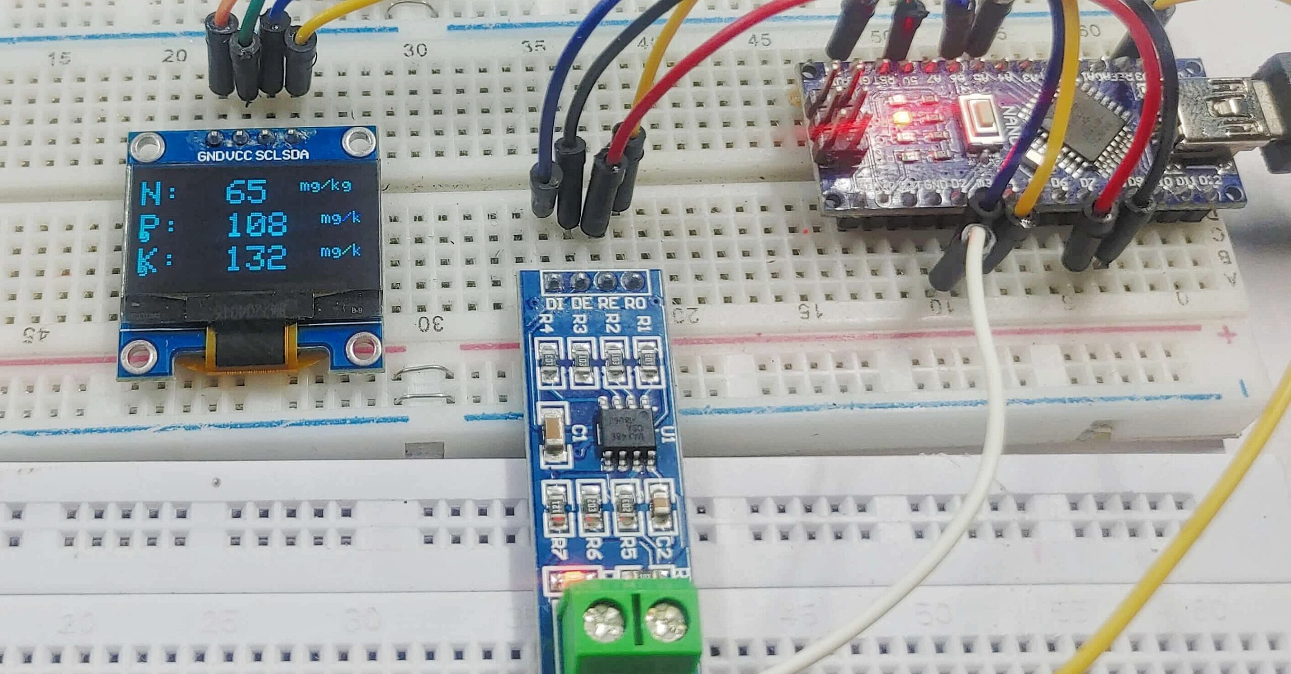
After uploading the code inserts the NPK sensor into soil that is wet or has high humidity. When inserted, it can be seen that the NPK (Nitrogen, Phosphorus, Potassium) value on the Display
Working
[Fix] Failed to read Data from NPK Sensor
If you are getting a value of 255 when trying to read data from an NPK sensor, it means that there is a problem with the communication between the sensor and your system. Here are a few things you can check to try and troubleshoot the issue:
- Make sure that all the connections between the NPK sensor and Arduino are properly connected.
- The MAX485 module should be powered by 5V and should have a common GND with other modules in the system.
- Check the slave address of the NPK sensor according to the datasheet or manual provided by the manufacturer in order to give the correct output.
- The NPK Sensor needs a supply voltage of at least 9 volts or 12 volts or more. Supply the appropriate voltage to the VCC pin. The sensor won’t work at a voltage lower than 9 volts.

